the Creative Commons Attribution 4.0 License.
the Creative Commons Attribution 4.0 License.
 | 24 Mar 2025
Research on the clock synchronization method of the marine controlled-source electromagnetic transmitter based on coaxial cable
Zhibin Ren
Meng Wang
Kai Chen
Chentao Wang
Runfeng Yu
The marine controlled-source electromagnetic (MCSEM) method is widely employed to reveal the electrical structure of shallow media below the seafloor. It is an indispensable geophysical means in the exploration of marine oil, gas, natural gas hydrates and seafloor geological structures. The transmitter and receiver in electromagnetic detection equipment need to maintain a high temporal consistency, typically relying on high-stability pulse-per-second (PPS) signals generated by GPS or BeiDou navigation modules. Coaxial cable is a widely used tow cable, so it is necessary to design a clock synchronization method of the marine controlled-source electromagnetic transmitter using coaxial cable. This paper proposes a method for synchronizing the internal clock of the transmitter with PPS using a ship-borne power supply when coaxial cable is used as a tow cable. In this method, the ship-borne high-voltage power supply outputs a high-voltage alternating current (AC) signal that is synchronized with a 400 Hz signal output from GPS; the coaxial cable transmits AC high-power electrical energy and control commands; and the AC signal transmitted via coaxial cable is converted into a stable and continuous 1 Hz signal by the step-down method, waveform shaping and frequency division for synchronizing the internal time pulses of the transmitter. The test result shows that the 1 Hz signal obtained by this method has a deviation of approximately 504 ns relative to PPS. This deviation meets the MCSEM transmitter's requirement for clock synchronization.
- Article
(1767 KB) - Full-text XML
- BibTeX
- EndNote


The marine controlled-source electromagnetic (MCSEM) method is one of the methods in the exploration of seafloor natural gas hydrates (Edwards and Chave, 1986; Cox et al., 1986). It is an indispensable geophysical means in the exploration of marine oil, gas, natural gas hydrates and seafloor geological structures (Constable and Srnka, 2007; Constable, 2010). In the MCSEM method, the synchronization of internal clocks between transmitter and receiver is a very important issue (Wang et al., 2015b; Meng et al., 2009). Electromagnetic data processing and interpretation depend on synchronization between transmitter and receiver (Qiu et al., 2020). The MCSEM transmitter and receiver are separated from each other (Chen et al., 2012, 2020), and they are not connected by any cable. Therefore, pulse-per-second (PPS) signal output from GPS is used as a common synchronization signal to synchronize the internal clock of the transmitter and receiver.
The tow cables commonly used in MCSEM transmission systems are photoelectric composite cables and coaxial cables. The transmitter's clock synchronization method varies based on the type of tow cable. When using coaxial cable as a tow cable, clock synchronization can be achieved by controlling the power supply output or transmitting PPS to the transmitter before it is submerged. As an example, the SUESI-500 transmitter of the Scripps Institution of Oceanography uses a standard UNOLS 0.680 in. (17.27 mm) coaxial cable as the tow cable. They use a 400 Hz output from a GPS clock to generate a 400 Hz sine wave of variable amplitude to control the power supply (Constable, 2013, 2006). The clock information in the power signal serves as a reference for clock-related operations within the transmitter. The SUESI-500 transmitter's frequency control signals are generated based on 400 Hz signal. When using a photoelectric composite cable as the tow cable, clock synchronization can be achieved by transmitting PPS through one channel of optical fiber. For example, the transmitter of China University of Geosciences (Beijing) uses a 32.8 mm photoelectric composite cable as the tow cable, and its clock synchronization is achieved by transmitting the PPS and GPS time through optical fiber (Wang et al., 2021). However, the cost of photoelectric composite cable is high, and generally only large scientific research ships can be equipped with it. In order to enable MCSEM transmitters work on a wider variety of ships, using coaxial cable is necessary. Compared to photoelectric composite cable, coaxial cable has only one message channel and cannot be assigned a separate channel to transmit PPS. The coaxial cable can transmit data and commands using power line communication, but its delay is unstable. If PPS is transmitted via coaxial cable, it will have a large deviation. Consequently, how to use coaxial cable to synchronize the internal clock of the MCSEM transmitter is a challenging problem. This paper proposes a clock synchronization method of the MCSEM transmitter based on coaxial cable. In this method, the sinusoidal signal from the power supply is synchronized with a 400 Hz square wave signal from GPS. Then the sinusoidal power signal transmitted to the underwater transmitter is converted into a stable and continuous 1 Hz square wave signal by the step-down method, waveform shaping and frequency division. The final 1 Hz square wave signal is like the synchronization signal for the transmitter's internal clock.
In this paper, the tow cable used is coaxial cable. This coaxial cable not only transmits electrical energy but also functions as a communication link between the deck monitoring terminal and the underwater transmitter. Communication is achieved through power line communication technology (Ferreira et al., 2001; Amuta et al., 2021; Kaddoum and Tadayon, 2016). The power transmitted through coaxial cable is a 400 Hz sinusoidal waveform.
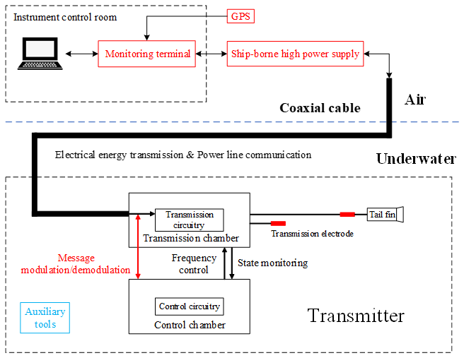
Figure 1 illustrates the schematic diagram of the MCSEM transmission system, which is based on coaxial cable. The ship is equipped with an instrument control room used to house a personal computer (PC) and the deck monitoring terminal. The deck monitoring terminal is connected to the ship-borne high-voltage power supply, allowing it to control power on/off functions and communication with the underwater transmitter. It also receives GPS time messages and PPS for clock synchronization. The ship-borne high-voltage power supply generates 0–3000 V, 400 Hz alternating current (AC) electricity to power the underwater transmitter (Wang et al., 2017b). In addition to transmitting electrical energy, the coaxial cable also transmits commands to the underwater transmitter by power line communication. The underwater transmitter consists of two main components: a transmission chamber and a control chamber. The transmission chamber contains step-down, rectification and inverter units, which transmit high-power electromagnetic waves to the seafloor (Wang et al., 2015a). The control chamber contains the control circuit of the entire transmitter, allowing it to transmit frequency-switching signals to control high-current transmissions and monitor the transmitter's state parameters. The transmitter is also equipped with auxiliary tools such as an altimeter and an attitude module to measure safety-related parameters during underwater towing. Behind the transmitter, two electrodes are towed, with a tail fin attached to the electrodes to stabilize their orientation (Wang et al., 2013, 2017a; Liu et al., 2012).
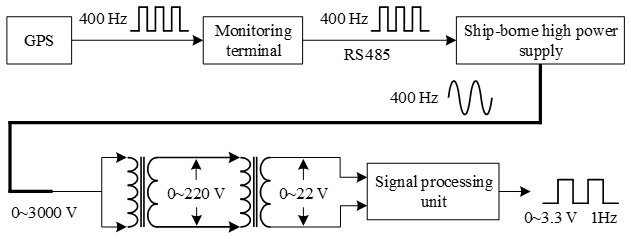
Figure 2 illustrates the synchronization signal flow based on coaxial cable. The GPS module features a TIMEPULSE pin that can be configured to output a 400 Hz square wave, with its rising edges precisely aligned with PPS at integer seconds. The 400 Hz square wave is transmitted to the ship-borne high-voltage power supply through the deck terminal as a synchronization signal. To prevent interference from the high-voltage power supply, the signal between the deck monitoring terminal and the power supply is transmitted via an isolated RS485 bus. The 400 Hz sinusoidal signal generated by the high-voltage power supply is transmitted to the underwater transmitter through coaxial cable, where it is converted to a sinusoidal signal in the range of 0–22 V by two transformers. The signal processing unit in the transmitter's control circuit processes the 0–22 V sinusoidal signal and generates a 1 Hz square wave as the synchronization signal for the control circuit. The rising edges of the 1 Hz square wave are aligned with the rising edges of PPS.
3.1 Deck monitoring terminal
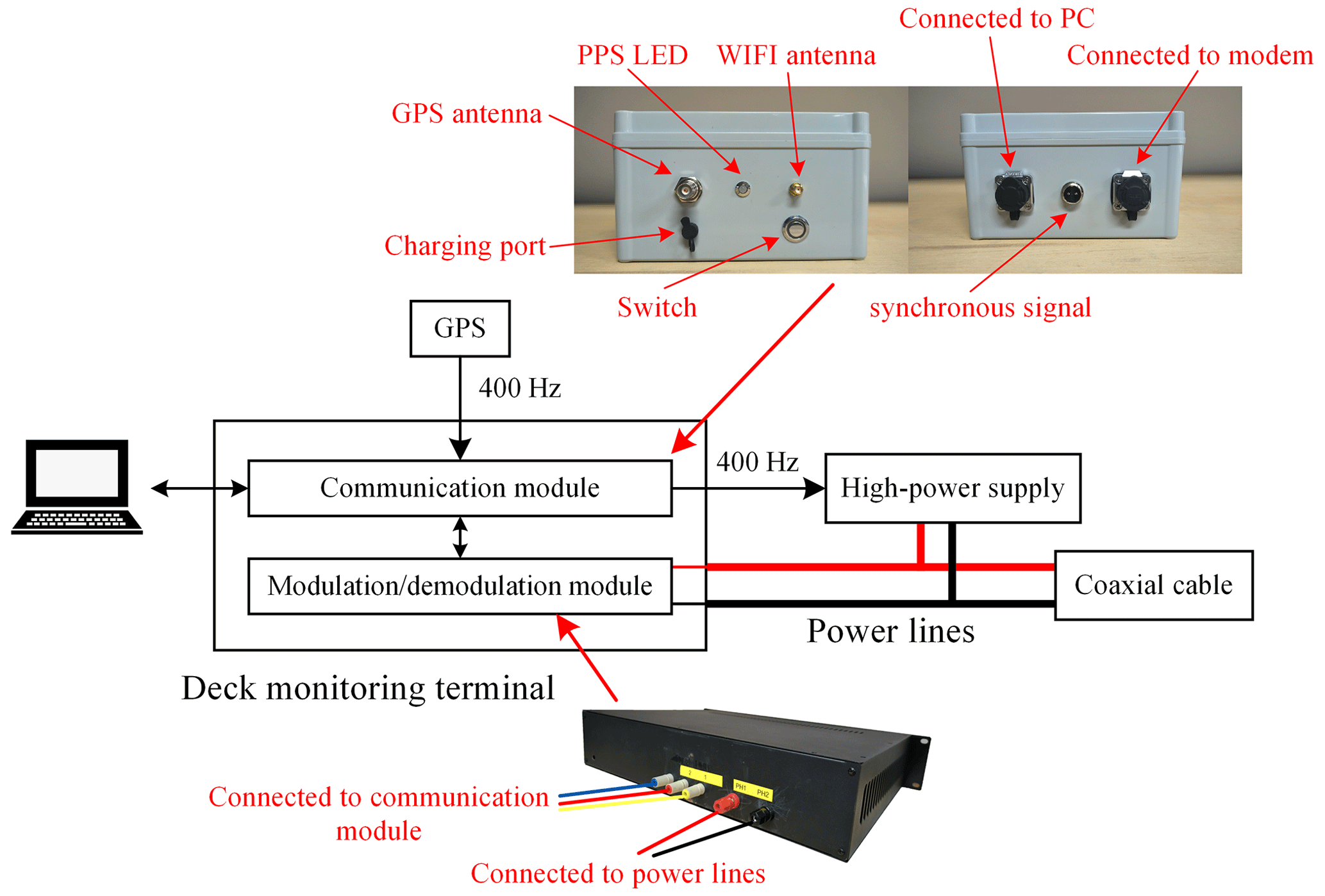
Figure 3 shows the block diagram of the deck monitoring terminal. The deck monitoring terminal comprises a communication module and a coaxial cable modulation/demodulation module (modem). The communication module is responsible for interactions between the monitoring software on the PC and the transmitter. A signal follower within the communication module receives the 400 Hz signal from GPS and relays it to the high-voltage power supply as a synchronization signal. The coaxial cable modem modulates messages sent by the PC via two power lines of coaxial cable and demodulates messages returned by the transmitter through coaxial cable.
3.2 High-voltage power supply output synchronized with GPS
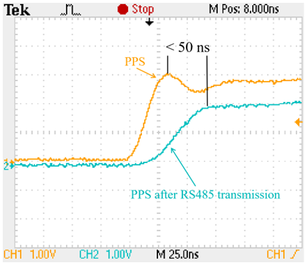
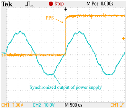
The high-voltage power supply is designed with a function to accept external synchronization signals. Both the underwater transformers of the transmitter and ship-borne high-voltage power supply operate at a frequency of 400 Hz. Accordingly, the TIMEPULSE pin of GPS is configured to output a 400 Hz signal and is connected to the high-voltage power supply via an RS485 module. This RS485 module will introduce a certain delay. Figure 4 shows the comparison of PPS before and after RS485 transmission. It is observed that the delay introduced by RS485 is less than 50 ns. The power supply output voltage is set to 20 V. The TIMEPULSE pin on another GPS is configured to output a 1 Hz signal, which is monitored alongside the power supply output. Figure 5 shows the synchronized output signal waveform of the power supply. It can be observed that the zero phase of the power supply output signal is aligned with the rising edge of PPS. After continuous observation, the 400 Hz sinusoidal signal output from the power supply remains stable relative to the rising-edge position of PPS. This synchronization of the power supply output is effective and forms the foundation of the entire clock synchronization method.
3.3 Signal processing unit
The 400 Hz sinusoidal signal output from the high-voltage power supply is transmitted to the transmitter via a coaxial cable. Then it passes through two transformers and is converted into a sinusoidal wave with an amplitude ranging from 0 to 24 V. This signal is converted into a 1 Hz square wave with an amplitude of 0 to 3.3 V by the signal processing circuit. Figure 6 shows the hardware of the signal processing unit.
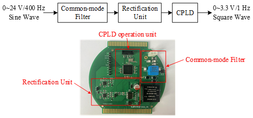
The 400 Hz sinusoidal wave, ranging from 0 to 24 V, is first processed by a common-mode filter to eliminate noise. A protective circuit consisting of gas discharge tubes (GDTs) and transient voltage suppression (TVS) diodes surrounds the common-mode-filter circuit to prevent overvoltage and protect subsequent stages. After filtering, the sinusoidal wave is processed through a rectification unit, which converts it into a 0–3.3 V, 400 Hz square wave signal. This rectification unit comprises an optical coupler and an operational amplifier, which rectifies signal, isolates input from output, and protects subsequent operational circuits from sudden variations in the input signal. The square wave signal from the rectifier is then processed by the operation unit of the underwater signal processing system, which generates a 1 Hz square wave using a pulse-counting method. The core of the operation unit is a complex programmable logic device (CPLD), which outputs one rising edge for every 400 counted rising edges of the 400 Hz square wave. The 1 Hz square wave output by the CPLD operation unit is the final synchronization signal transmitted to the control circuit.
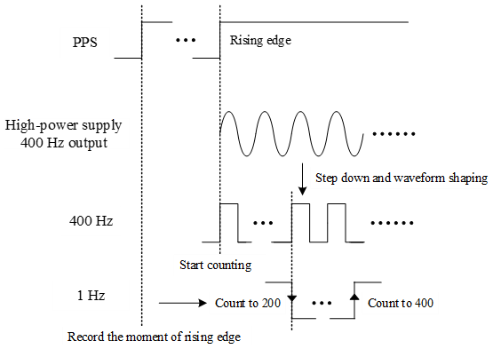
To align the rising edges of the 1 Hz square wave with the rising edges of PPS, the CPLD module records the exact moment of the PPS rising edges. The 1 Hz square wave is aligned with PPS only when CPLD begins counting the 400 Hz square wave at the moment of a certain PPS rising edge. Therefore, before submerging the transmitter, an external GPS module is connected to it. Once CPLD records the timing of the PPS rising edges, it generates an internal 1 Hz signal synchronized with PPS. Afterward, the external GPS module is removed, and the power supply is activated. The CPLD module initially sets the output pin to low and then raises it to high upon detecting the first rising edge of the internally generated 1 Hz signal, as illustrated in Fig. 7. After this, when the rising edge count of the 400 Hz signal reaches 200, the output pin is set to low, generating a falling edge; when the count of the 400 Hz signal reaches 400, the output pin is set to high, generating a rising edge and resetting the counter for the next cycle. The clock synchronization of the entire transmitter system depends on the rising edges of PPS, which must be generated with accuracy and stability. Therefore, this method of counting rising edges of the 400 Hz signal directly to 400 ensures the precise generation of these rising edges.
No matter which clock synchronization method is used, there will be a deviation between the final 1 Hz square wave signal generated and the PPS from GPS. The main deviation in the conventional MCSEM clock synchronization method comes from the crystal oscillator inside the transmitter. The generation of the 1 Hz signal synchronized with the rising edges of PPS relies on internal crystal oscillator. If the temperature drift of the crystal is smaller, the frequency of the output signal is more stable and the clock synchronization deviation is also smaller. The clock synchronization method in this paper generates a 1 Hz signal synchronized to the rising edges of PPS by counting the rising edges of the 400 Hz square wave. Its frequency stability primarily is from the stability of the 400 Hz output of the power supply, reducing dependence on the internal crystal oscillator. The deviation of this method comes from circuit processing, cable transmission and other stages that may generate signal delay, and it can be calculated by the following formula:
where T is the delay of the generated 1 Hz square wave signal relative to PPS, T1 is the delay generated by the circuit processing stage, T2 is the delay generated by cable transmission, and T3 is the delay caused by the signal passing through the transformers. T1 mainly consists of three parts: chip program processing, signal transmission in all circuitry and the synchronization process of the power supply. T1 can be calculated by the following formula:
where Tc is the instruction cycle of the chip, i.e., the time required to execute one instruction; n is the number of instructions; t1 is the delay caused by the signal transmission in all circuitry; t2 is the delay generated by the high-voltage power supply synchronization output; and Tc is related to the crystal oscillator used by the chip. In this paper, the value of Tc is 6 ns, and the value of n does not exceed 30. t1 is related to the components used in the signal transmission path in the circuit board. In this paper, the value of t1 does not exceed 4 ns. There is a slight delay in the zero phase of the 400 Hz signal from the power supply relative to the rising edges of the 400 Hz synchronization signal, but the power supply output signal waveform is not a standard sine wave, making it difficult to precisely identify the zero phase. Therefore, it is difficult to obtain an accurate result for t2 through a separate test, but a subsequent overall deviation test includes t2; t2 mainly consists of three parts: the delay caused by coaxial cable transmission and delay caused by wire transmission between circuit boards, and it can be calculated by the following formula:
where Lcable is the length of coaxial cable, vcable is the speed at which the signal is transmitted via coaxial cable, Lwire is the length of wires between circuit boards, vwire is the speed at which the signal is transmitted via wires, c is the speed of light in a vacuum, η1 is the ratio of the signal transmission speed on coaxial cable to the speed of light in a vacuum, and η2 is the ratio of the signal transmission speed between circuit boards via wires to the speed of light in a vacuum. The typical value of η1 ranges from 0.67 to 0.75, and the typical value of η2 ranges from 0.6 to 0.9 (when using 22 AWG wire). Therefore, for every 1 km of coaxial cable, the delay typically falls within a range of 4.48 to 4.98 µs. The total length of wires between circuit boards inside the transmission chamber does not exceed 1 m, resulting in a delay typically ranging from 3.7 to 5.56 ns.
The 400 Hz signal output from the high-voltage power supply passes through two stages of the transformers and is reduced to a low voltage ranging from 0 to 22 V for processing by the underwater signal processing unit. The transformers are not ideal transformers, so there is a certain phase shift between the primary input voltage and the secondary output voltage of each transformer, which is the cause of T3. Due to limited test condition, T3 cannot be tested separately in this paper, but subsequent overall deviation testing includes T3. All deviations described above can be combined and measured in the overall test of the clock synchronization method.
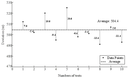
Figure 11The graph of multiple test results for synchronization deviation shows the difference between each result and the average value.
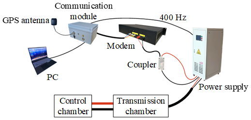
In accordance with the clock synchronization method using the power supply signal based on coaxial cable, as discussed in this paper, a test platform was built in a laboratory to evaluate the effectiveness of clock synchronization. The test setup is shown in Fig. 8. Due to the high-voltage output of the power supply and the low-voltage requirement of the modem, a coupler is needed to connect the two (Giraneza and Abo-Al-Ez, 2022; Costa et al., 2017). This coupler is a capacitive coupler, which presents significant impedance to the 400 Hz AC signal. Consequently, the voltage in the power carrier loop primarily accumulates at the coupler's ends. Since the frequency of the power line communication exceeds 100 kHz, the coupler's impedance is relatively low. Therefore, the power line communication signal can pass through the coupler, but the 400 Hz synchronization signal of the high-voltage power supply does not. This coupler does not cause a delay.
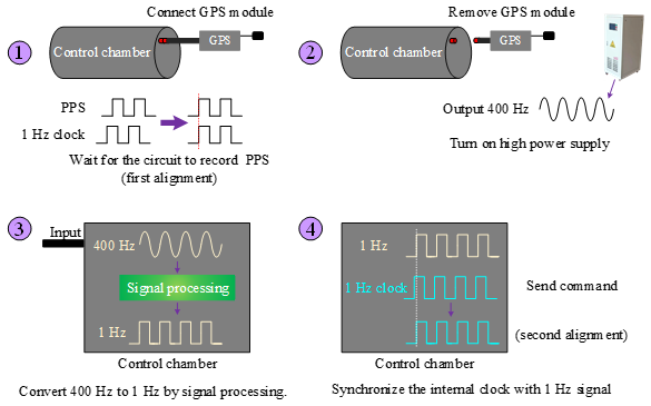
Figure 9 shows the clock synchronization process based on coaxial cable. First, the control chamber is connected to a GPS module. Once the control circuit receives PPS and records the specific timing of the rising edges, the GPS module is removed. Next, the high-voltage power supply is activated. The 400 Hz AC signal output from the power supply is converted into a 1 Hz square wave by the signal processing unit inside the control chamber. Finally, the PC sends a synchronization command, and the transmitter's internal clock realigns with the 1 Hz square wave.
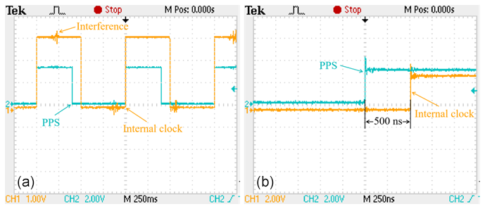
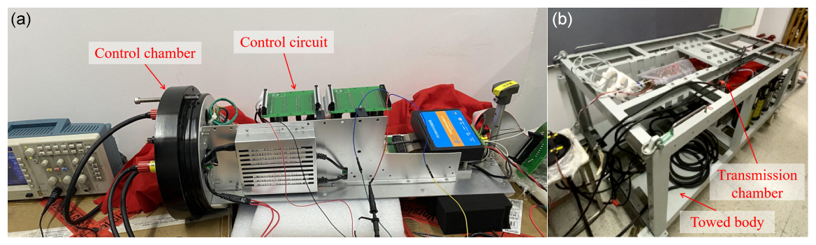
Figure 10 shows the internal clock synchronized with PPS and the clock synchronization deviation. To facilitate observation, the duty cycle of the internal clock signal generated by the underwater signal processing unit was set to 50 %, while the duty cycle of PPS output from the GPS module was set to 40 %. After continuous observation, the deviation between the rising edge of the internal clock signal and the rising edge of PPS was approximately 504 ns. Figure 11 presents the results of multiple tests, showing that the synchronization deviation fluctuated around 504 ns with a range of 34 ns. The coaxial cable used in the test was relatively short. In marine operations, a 10 km length of coaxial cable can introduce a maximum delay of approximately 49.8 µs. In this case, the maximum delay of the internal clock signal relative to PPS would be approximately 50.3 µs. During the measurement of the internal clock signal, some interference pulses were observed, likely caused by test pins being too close to high-power equipment in the laboratory environment. Figure 12 shows some photos of the test scene.
Unlike the Scripps transmitter, this study employs a ship-borne high-voltage power supply to transmit a 400 Hz signal and generate a 1 Hz square wave synchronized with PPS as the synchronization signal for the transmitter circuit. The transmission waveform frequency control signal is generated based on the internal crystal oscillator of the circuit, with its rising edge aligned with the rising edge of the 1 Hz synchronization signal.
This paper introduces a clock synchronization method of the marine controlled-source electromagnetic transmitter based on coaxial cable and builds a related hardware system. In this method, the ship-borne high-voltage power supply outputs a 400 Hz signal synchronized with PPS and transmits it to an underwater transmitter. The transmitter control circuit can generate a 1 Hz square wave signal synchronized with PPS for clock synchronization. The delay deviation of the 1 Hz square wave signal obtained by this method relative to PPS is less than 1 ms, which meets the requirement of synchronization accuracy better than 1 ms in practical operations and can be used for the internal clock synchronization of the transmitter. This method can facilitate the use of coaxial cables in MCSEM operations and expand transmitter's application scenarios. This method can also provide a reference for the design of other underwater equipment that uses coaxial cables.
No data sets were used in this article.
MW is the project applicant and a key participant in the testing process. KC provided some optimization suggestions for the test scheme. CW and RY, as the research assistants, helped complete the testing. ZR is the project leader, primarily responsible for the test scheme design, hardware circuit design and other related tasks.
The contact author has declared that none of the authors has any competing interests.
Publisher's note: Copernicus Publications remains neutral with regard to jurisdictional claims made in the text, published maps, institutional affiliations, or any other geographical representation in this paper. While Copernicus Publications makes every effort to include appropriate place names, the final responsibility lies with the authors.
We thank the editors and reviewers. Additionally, this paper was supported by South China Sea Institute of Oceanology (CAS) and the Fujian Earthquake Agency. The authors express thanks to the two mentioned institutions.
This research has been supported by the National Natural Science Foundation of China (grant no. 42374221), the Key Technologies R&D Program (grant no. 2022YFC2807900), and the Marine Economic Development in Guangdong Province (grant no. GDNRC[2023]40).
This paper was edited by David Barclay and reviewed by two anonymous referees.
Amuta, E., Awelewa, A., Olajube, A., Somefun, T., Afolabi, G., and Uyi, A.: Power line carrier technologies: a review, IOP Conference Series: Materials Science and Engineering, 2nd International Conference on Sustainable Infrastructural Development (ICSID 2020), 27–28 July 2020, Ota, Nigeria, Volume 1036, 012062, https://doi.org/10.1088/1757-899X/1036/1/012062, 2021.
Chen, K., Deng, M., Wu, Z., Jing, J., Luo, X., and Wang, M.: Low Time Drift Technology for Marine CSEM Recorder, Geoscience, 26, 1312–1316, https://doi.org/10.3969/j.issn.1000-8527.2012.06.027, 2012.
Chen, K., Deng, M., Yu, P., Yang, Q., Luo, X. H., and Yi, X. P.: A near-seafloor-towed CSEM receiver for deeper target prospecting, Terr. Atmos. Ocean. Sci., 31, 565–577, https://doi.org/10.3319/tao.2020.08.03.01, 2020.
Constable, S.: Marine electromagnetic methods – A new tool for offshore exploration, The Leading Edge, 25, 438–444, https://doi.org/10.1190/1.2193225, 2006.
Constable, S.: Ten years of marine CSEM for hydrocarbon exploration, Geophysics, 75, 75A67–75A81, https://doi.org/10.1190/1.3483451, 2010.
Constable, S.: Review paper: Instrumentation for marine magnetotelluric and controlled source electromagnetic sounding, Geophys. Prospect., 61, 505–532, https://doi.org/10.1111/j.1365-2478.2012.01117.x, 2013.
Constable, S. and Srnka, L. J.: An introduction to marine controlled-source electromagnetic methods for hydrocarbon exploration, Geophysics, 72, WA3–WA12, https://doi.org/10.1190/1.2432483, 2007.
Costa, L. G. D. S., Queiroz, A. C. M. D., Adebisi, B., Costa, V. L. R. D., and Ribeiro, M. V.: Coupling for power line communications: A survey, Journal of Communication and Information Systems, 32, 8–22, https://doi.org/10.14209/jcis.2017.2, 2017.
Cox, C., Constable, S., Chave, A., and Webb, S.: Controlled-source electromagnetic sounding of the oceanic lithosphere, Nature, 320, 52–54, https://doi.org/10.1038/320052a0, 1986.
Edwards, R. and Chave, A.: A transient electric dipole-dipole method for mapping the conductivity of the sea floor, Geophysics, 51, 984–987, https://doi.org/10.1190/1.1442156, 1986.
Ferreira, H. C., Grové, H. M., Hooijen, O., and Vinck, A. H.: Power line communication, Wiley Encyclopedia of Electrical and Electronics Engineering, 16, 706–716, https://doi.org/10.1002/047134608X.W2004, 2001.
Giraneza, M. and Abo-Al-Ez, K.: Power line communication: A review on couplers and channel characterization, AIMS Electronics and Electrical Engineering, 6, 265–284, https://doi.org/10.3934/electreng.2022016, 2022.
Kaddoum, G. and Tadayon, N.: Differential chaos shift keying: A robust modulation scheme for power-line communications, IEEE T. Circuits-II, 64, 31–35, https://doi.org/10.1109/TCSII.2016.2546901, 2016.
Liu, Y., Yin, C., Weng, A., and Jia, D.: Attitude effect for marine CSEM system, Chinese J. Geophys., 55, 2757–2768, https://doi.org/10.6038/j.issn.0001-5733.2012.08.027, 2012.
Meng, W., Ming, D., Qi-sheng, Z., Kai, C., and Jin-ling, C. U. I.: The technique of time synchronization operation to control marine electromagnetic emission, Progress in Geophysics, 24, 1493–1498, https://doi.org/10.3969/j.issn.1004-2903.2009.04.043, 2009.
Qiu, Y., Yang, Q., Deng, M., and Chen, K.: Time synchronization and data transfer method for towed electromagnetic receiver, Rev. Sci. Instrum., 91, 094501, https://doi.org/10.1063/5.0012218, 2020.
Wang, M., Zhang, H.-Q., Wu, Z.-L., Sheng, Y., Luo, X.-H., Jing, J.-E., and Chen, K.: Marine controlled source electromagnetic launch system for natural gas hydrate resource exploration, Chinese J. Geophys., 56, 3708–3717, https://doi.org/10.6038/cjg20131112, 2013.
Wang, M., Deng, M., Zhao, Q., Luo, X., and Jing, J.: Two types of marine controlled source electromagnetic transmitters, Geophys. Prospect., 63, 1403–1419, https://doi.org/10.1111/1365-2478.12329, 2015a.
Wang, M., Wu, Z.-L., Deng, M., Ma, C.-W., Liu, Y., and Wang, S.-X.: The high precision time stamp technology in MCSEM transmission current waveform, Progress in Geophysics, 30, 1912–1917, https://doi.org/10.6038/pg20150452, 2015b.
Wang, M., Deng, M., Wu, Z.-L., Luo, X.-H., Jing, J.-E., and Chen, K.: New type deployed marine controlled source electromagnetic transmitter system and its experiment application, Chinese J. Geophys., 60, 4253–4261, https://doi.org/10.1111/1365-2478.12329, 2017a.
Wang, M., Deng, M., Wu, Z., Luo, X., Jing, J., and Chen, K.: The deep-tow marine controlled-source electromagnetic transmitter system for gas hydrate exploration, J. Appl. Geophys., 137, 138–144, https://doi.org/10.1016/j.jappgeo.2016.12.019, 2017b.
Wang, M., Ming, D., Li, X., Zhang, Z., Yue, H., Zhang, T., Duan, N., and Ma, X.: The latest development of Marine controllable source electromagnetic transmitter, IOP Conference Series: Earth and Environmental Science, The 9th International Conference on Environmental and Engineering Geophysics, 11–14 October 2020, Changchun, China, Volume 660, 012137, https://doi.org/10.1088/1755-1315/660/1/012137, 2021.
- Abstract
- Introduction
- Clock synchronization based on coaxial cable
- Hardware design of clock synchronization method based on coaxial cable
- Analysis of clock synchronization deviation
- The test of clock synchronization method
- Conclusion
- Data availability
- Author contributions
- Competing interests
- Disclaimer
- Acknowledgements
- Financial support
- Review statement
- References