the Creative Commons Attribution 4.0 License.
the Creative Commons Attribution 4.0 License.
 | 23 Aug 2022
Tesseract – a high-stability, low-noise fluxgate sensor designed for constellation applications
Christian Hansen
B. Barry Narod
Richard Dvorsky
David M. Miles
Accurate high-precision magnetic field measurements are a significant challenge for many applications, including constellation missions studying space plasmas. Instrument stability and orthogonality are essential to enable meaningful comparison between disparate satellites in a constellation without extensive cross-calibration efforts. Here we describe the design and characterization of Tesseract – a fluxgate magnetometer sensor designed for low-noise, high-stability constellation applications. Tesseract's design takes advantage of recent developments in the manufacturing of custom low-noise fluxgate cores. Six of these custom racetrack fluxgate cores are securely and compactly mounted within a single solid three-axis symmetric base. Tesseract's feedback windings are configured as a four-square Merritt coil to create a large homogenous magnetic null inside the sensor where the fluxgate cores are held in a near-zero field, regardless of the ambient magnetic field, to improve the reliability of the core magnetization cycle. A Biot–Savart simulation is used to optimize the homogeneity of the field generated by the feedback Merritt coils and was verified experimentally to be homogeneous within 0.42 % along the racetrack cores' axes. The thermal stability of the sensor's feedback windings is measured using an insulated container filled with dry ice inside a coil system. The sensitivity over temperature of the feedback windings is found to be between 13 and 17 ppm ∘C−1. The sensor's three axes maintain orthogonality to within at most 0.015∘ over a temperature range of −45 to 20 ∘C. Tesseract's cores achieve a magnetic noise floor of 5 pT √Hz−1 at 1 Hz. Tesseract will be flight demonstrated on the ACES-II sounding rockets, currently scheduled to launch in late 2022 and again aboard the TRACERS satellite mission as part of the MAGIC technology demonstration which is currently scheduled to launch in 2023.
- Article
(4009 KB) - Full-text XML
- BibTeX
- EndNote


Constellation satellite missions have an important role in the future of space plasma science. The NASA Heliophysics Science and Technology Roadmap for 2014–2033 states that a driver of scientific discovery will come from a constellation mission of 30 or more spacecraft (Heliophysics Roadmap 2014). Recent missions such as Cluster (Balogh et al., 2001), Swarm (Merayo et al., 2008), Space Technology 5 (Slavin et al., 2008), Time History of Events and Macroscale Interactions during Substorms (Auster et al., 2008) and the Magnetospheric Multiscale Mission (Torbert et al., 2016) have successfully flown constellations of three to five spacecraft and have made significant contributions to the understanding of solar wind and magnetospheric physics (Ganushkina et al., 2017; Nakariakov et al., 2016, and references therein). The environmental conditions experienced over the course of these magnetospheric constellation missions are representative for almost all spaceborne magnetometers; they are subject to a wide range of magnetic fields (low field at apogee, high field at perigee), radiation exposures, and temperature changes due to eclipse crossings.
Recent developments in nanosatellite technology promise to provide a platform for the future of constellation missions at a low cost (Bandyopadhyay et al., 2015). Such a nanosatellite constellation mission could accurately resolve and characterize the spatial and temporal evolution of magnetic fluctuations that are indicative of larger-scale magnetospheric processes, such as plasma waves, field-aligned currents, and plasma transport at various scales. However, constructing a magnetic sensor with sufficiently small mass and volume to be accommodated on a nanosatellite while still maintaining the instrumental accuracy and precision required for a magnetospheric constellation mission is not a trivial task. As the size of a fluxgate sensor is reduced, it becomes increasingly difficult to preserve the stability required for reliable multi-point cross-comparisons. This presents a significant challenge for the use of nanosatellites on constellation missions. The 2015 NASA Technology Roadmap has noted the importance of addressing the challenge of “high measurement stability to allow inter-satellite calibration” to enable “high-stability magnetic field measurements that can be made in distributed systems” (2015 NASA Technology Roadmap 8.3.1.3).
1.1 Fluxgate sensor stability
Fluxgate magnetometers do not measure the magnetic field absolutely and therefore must be calibrated in order to make accurate measurements. However, the calibration parameters sensitivity, orthogonality, and offset vary with changes in temperature or over time. Fluxgate stability is the degree to which these calibration parameters remain constant. Fluxgate stability is critically important for a magnetospheric constellation mission, as it enables comparison of disparate magnetic measurements without the need for intensive cross-calibration. However, it remains poorly understood and is not explicitly addressed by many authors in the literature. Fluxgate offsets are thought to originate primarily from the cores and driving electronics (Ripka et al., 2014), while changes in sensitivity and orthogonality are caused predominately by changes in the geometry of the sensor (Acuña et al., 1978; Miles et al., 2017). In this paper, we are concerned with the stability of the sensor. Factors suspected of degrading a fluxgate sensor's stability include an inhomogeneous magnetic null (Ripka, 1992) and skewing of the axes due to mechanical and thermal strain (Primdahl, 1979).
Fluxgate magnetometers (Primdahl, 1979) measure the static and low-frequency vector magnetic field by modulating or gating the local magnetic flux and measuring the induced electromagnetic force (EMF) in a sense winding. A ferromagnetic core, periodically driven into magnetic saturation at frequency f, is used to gate the local field, thereby inducing a second harmonic (2f) signal due to the nonlinear magnetic permeability of the core as it enters magnetic saturation twice per cycle. In this paper, we will be discussing only second harmonic fluxgates. In many instruments, including that presented here, magnetic feedback is used to null the magnetic field in the sensor, which linearizes and extends the measurement range of the instrument and is thought to improve overall fluxgate stability (Primdahl and Jensen, 1982). Our magnetic sensors that are nulled on two axes, such as the CASSIOPE/e-POP fluxgate which maintained a sensitivity stability of approximately 18 ppm ∘C−1 (i.e., Wallis et al., 2015; Miles et al., 2013), outperform our sensors zeroed in only a single component (i.e., Narod and Bennest, 1990; Acuña et al., 1978) which achieved a stability of 26 ppm ∘C−1 over the temperature range from −20 to 40 ∘C. Thus, we hypothesize that a null on all three axes will further improve stability compared with one- or two-axis nulled sensor designs.
1.2 Current state of high-stability constellation fluxgate sensors
Recent constellation missions have increasingly focused on flying three-axis compensated sensors in the interest of maximizing instrumental stability. However, sensor designs that have flown on past constellation missions have been constrained to accommodating a traditional one-inch diameter ring-core geometry ferromagnetic core.
Potentially the most stable magnetospheric field fluxgate measurements to date were taken with the Compact Spherical Coil (CSC) Sensor aboard Swarm which implements a nested three-axis feedback coil wound on a MACOR shell to create a very homogenous three-axis null at the locations of the cores. From Primdahl and Jenson (1982), we estimate that the CSC's feedback coils hold their ring cores in a field that deviates from uniformity by 1.5 %. The mm, 500 g CSC sensor has maintained a sensitivity stability over temperature of 10 ppm ∘C−1 and a very high axis stability of 0.002∘ from −20 to 40 ∘C while achieving a noise floor of 6.6 pT √Hz−1 at 1 Hz (Merayo et al., 2008).
The THEMIS mission incorporated mm, 75 g, low-mass fluxgate sensors that achieved a sensitivity stability of 22 ppm ∘C−1, an axis stability within 0.017∘ from −100 to 60 ∘C and a noise of 10 pT Hz−1 at 1 Hz (Auster et al., 2008). The mm, 88 g Magnetospheric Multiscale Mission Direct Fluxgate instrument achieved a sensitivity stability over temperature of 30 ppm ∘C−1, an axis stability of about 0.03∘ between −50 and 30 ∘C, and a noise floor of 8 pT √Hz−1 at 1 Hz (Russell et al., 2016). Notably, the temperature-dependent sensitivity can be corrected to first order by fluxgate electronics using a compensated feedback current (Primdahl, 1970; Acuña et al., 1978; Miles et al., 2017); however, no equivalent compensation exists for orthogonality. In general, smaller temperature-dependent sensitivity is desirable, but smaller orthogonality dependence is more critical.
Future constellation missions, such as the Geospace Dynamics Constellation (Pfaff, 2016), MagneToRE (Maruca et al., 2021), and NanoSWARM (Garrick-Bethell et al., 2021), promise to build on the success of these constellation magnetometers, and the continued development of increasingly precise, robust, magnetic field instruments remains an important means in these efforts.
1.3 Current state of miniaturized fluxgate sensors
Nanosatellites as a platform for magnetospheric measurements are an emerging topic in the literature. Some tend to focus on miniaturizing traditional fluxgate magnetometer designs for CubeSat applications without overly compromising their measurement capability (e.g., Ripka, 2003, and references therein). Recent missions, such as Dellingr and ExAlta1, have implemented miniaturized, boom-deployed fluxgate magnetometers on nanosatellites. The Dellingr nanosatellite flew a very small 19 g fluxgate magnetometer with a noise floor of 120 pT √Hz−1 at 1 Hz (Kepko et al., 2017). The ExAlta1 CubeSat flew a 47 g miniaturized fluxgate sensor with a noise floor of 150 pT √Hz−1 at 1 Hz (Miles et al., 2016). However, these miniature instruments typically sacrifice noise and stability in the interest of small size. With a sensitivity stability poorer than 50 ppm ∘C−1, these sensors function primarily as variometers. If used in a constellation setting, measurements from disparate sensors would be far less comparable than those from a previous constellation mission without complex and time-consuming cross-calibration. One of the best small sensors to date appears to be the Small Magnetometer in Low-mass Experiment (SMILE): a mm, 40 g cubic sensor based on three rod cores within a three-axis feedback winding, which achieved a thermal sensitivity stability of 11 ppm ∘C−1, an axis stability better than 0.02∘ from −30 to 45 ∘C, and 30 pT √Hz−1 at 1 Hz (Forslund et al., 2008).
1.4 Tesseract sensor overview
Like the CSC and SMILE sensors, Tesseract's feedback windings create a three-axis “magnetic null” inside the sensor where the fluxgate cores are held in the near-zero field. This ensures that the cores do not exceed their linear sensitivity region regardless of the magnitude of the ambient magnetic field (Primdahl and Jensen, 1982). An inhomogeneous magnetic null at the cores is thought to contribute to degradation of the stability of a fluxgate's offset (Ripka, 1992), sensitivity (Korepanov and Marusenkov, 2012), and orthogonality (Petrucha et al., 2015).
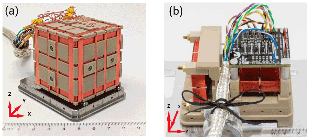
Figure 1(a) A high-fidelity prototype of the Tesseract sensor has been constructed for testing in preparation for MAGIC: a technology demonstration of the TRACERS satellite mission's Tesseract feedback coils is arranged in a three-axis four-loop Merritt coil which is expected to create a large homogenous null region in the sensor. Tesseract's feedback coils are wound on a common base of 30 % glass-filled Torlon. (b) A two-axis null ring-core sensor design based on Miles et al. (2013) was used in the testing described in Sect. 3 and is shown for comparison.
Here, we present the design and characterization of Tesseract: a high-stability fluxgate magnetometer for constellation missions. The Tesseract sensor's three-axis feedback windings are arranged in a four-square Merritt coil, which creates a proportionally larger homogeneous region than the Helmholtz coil for the same external volume (Merritt et al., 1983), allowing it to accommodate more cores (six instead of three). The idea of more complex feedback winding is not new. Designs such as Primdahl and Jensen (1982), Auster (2008), and Chulliat (2009) have used different methods of stacking concentric circular coils to create a three-axis null sensor. A study by Petrucha et al. (2015) experimented with a laboratory prototype sensor that used a Merritt coil feedback topology with ring geometry cores. Tesseract's design draws inspiration from the aforementioned SMILE sensor (Forslund et al., 2008), which used three equally spaced square feedback coils and a parallel rod sensor in each axis to create a cube-shaped, three-axis nulled sensor. Tesseract's Merritt coil feedback winding has been optimized to hold six racetrack cores within a highly homogeneous null field (deviations from the average of less than 0.42 %), which allows for a reproducible magnetization of the ferromagnetic cores. This reproducibility is designed to improve the measurement stability (Ripka et al., 2014; Korepanov and Marusenkov, 2012) and linearity (Brauer et al., 1997) of the sensor.
Table 1The Tesseract sensor's specifications as measured in the laboratory compared with the specifications of a more traditional ring-core sensor design described in Miles et al. (2013). Tesseract is marginally larger than the Miles et al. (2013) ring-core sensor design but has much higher axis stability and magnetic feedback homogeneity, which are associated with higher instrumental stability. The uncompensated stability and orthogonality angles are both measured from −45 to 20∘.
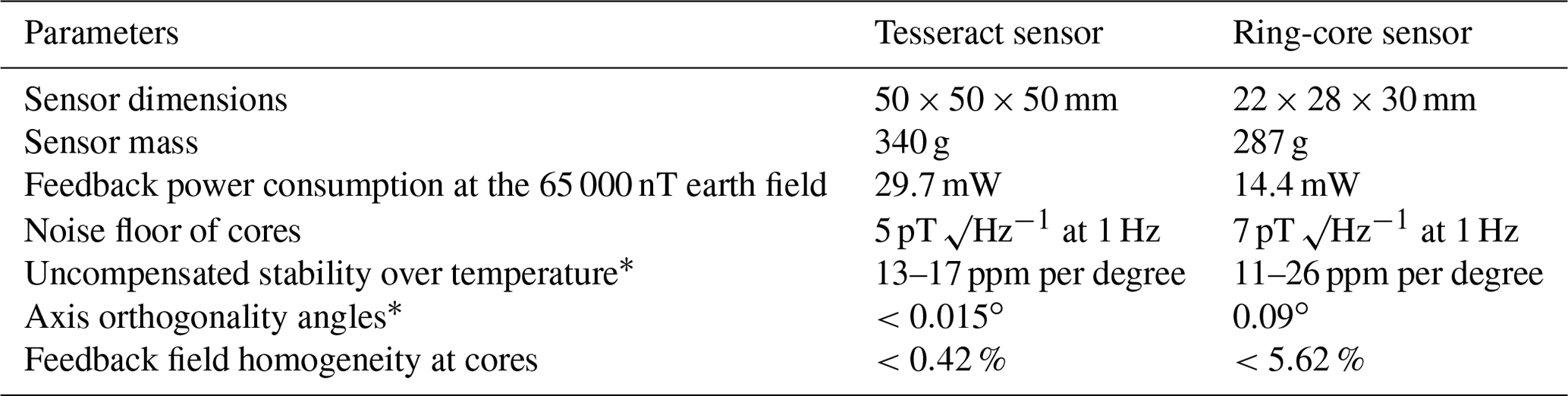
* In the range from −45 to 20∘ C.
Tesseract's custom low-noise racetrack geometry cores are securely and compactly mounted within a single solid three-axis symmetric base of 30 % glass-filled Torlon, reducing the potential for mechanical strains due to uneven coefficients of linear expansion and reducing the tendency of the sensor to skew with temperature, thus limiting these potential sources of instrument instability. Tesseract's cores achieve a magnetic noise floor of 5 pT √Hz−1 at 1 Hz, an orthogonality within 0.015∘, and a temperature stability of 13–17 ppm ∘C−1 between −45 and 20∘.
Tesseract is designed to mitigate known sources of instability such as an uncompensated residual field inside the sensor and skewing of the axes and the cores due to mechanical and thermal stresses while still maintaining low noise and a small size. Here we describe the design, optimization, manufacturing, and assembly processes for the Tesseract sensor.
2.1 Racetrack core design
The noise floor of a fluxgate is typically limited by the intrinsic magnetic noise of a permalloy core that is periodically driven into magnetic saturation to modulate the local magnetic field. Recent development in custom low-noise core manufacturing by Miles et al. (2019) enabled us to create custom low-noise miniature racetrack sensors (Miles et al., 2022).
Custom permalloy created using the Miles et al. (2022) process is cold-rolled into 50 µm-thick foil. The permalloy foil is then cut to 5 cm length, stacked, drilled, and secured in a tight bundle. A milling machine was used to machine 6.45 mm-wide by 31.45 mm-long racetrack foil washers. The racetrack washers are placed in the furnace, heat-treated, and stacked into a Torlon bobbin (Fig. 2a) and interleaved with insulating layers of Kapton of the same geometry.
Production cores are interleaved with a polymer between the foil layers to prevent them from moving during the magnetizing drive pulses. A plastic lid closes the core and serves as a base upon which to wind a quasi-toroidal drive of AWG 32 magnet wire (Fig. 2b). Finally, a solenoidal sense winding of AWG 34 magnet wire is wrapped around the length of the base.
The stacked foil washers remove the need to spot-weld, as is done in traditional spiral-wound sensors, avoiding the heat-affected area around the weld and its unpredictable magnetic properties. Heat-treating the foil washers individually removes the risk of undesired welding between layers that can cause unintended shorting. The racetrack geometry aligns ferromagnetic mass on one axis, producing lower noise. However, the racetrack geometry cannot be double-wound like a ring core to sample two orthogonal components. The closed flux path of the racetrack should reduce stray fields and offset error compared with traditional parallel rod sensors (e.g., Janosek, 2017; Moldovanu et al., 2000).
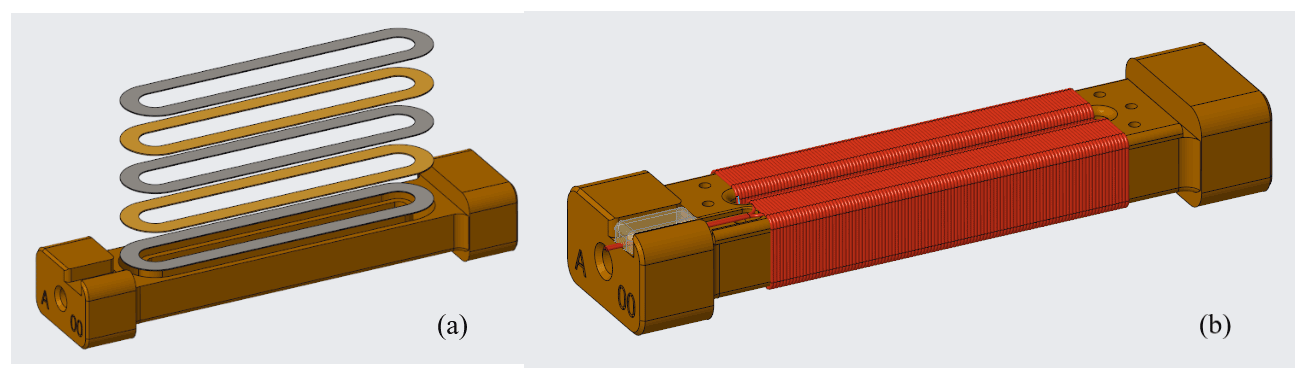
Figure 2(a) Layers of foil loops are stacked within a Torlon bobbin with a layer of Kapton placed in between permalloy layers. (b) The bobbin serves as a frame for the drive coils which are wound on the two long racetrack supports.
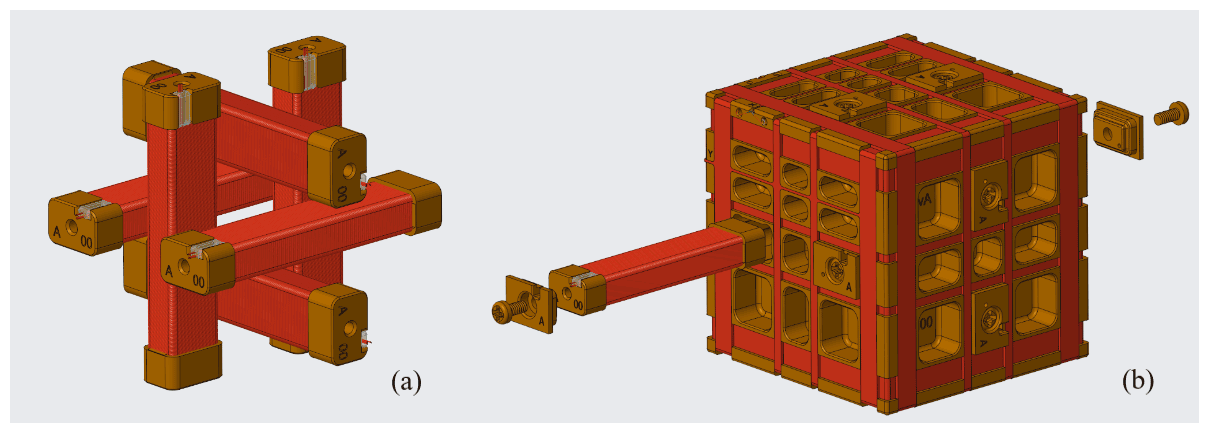
Figure 3(a) Tesseract's six miniature racetrack cores are wound with a solenoidal sense winding, arranged in pairs/two per axis and (b) secured within one common Torlon base. The Tesseract sensor's Merritt coil feedback windings are wound in small, machined channels in this base.
2.2 Sensor base design
Tesseract leverages this racetrack geometry to create a compact sensor. Six of these custom racetrack geometry cores are fixed within a three-axis symmetric 30 % glass-filled polyamide-imide (Torlon 5030) base in a compact configuration of two cores per axis shown in Fig. 3a. We hypothesize that pairing of identical cores with opposite polarities in each axis may further reduce the tendency for cross-axis contamination due to mutual cancellation of their stray fields (Ripka and Billingsley, 2000).
These cores are then secured firmly in place using polymerics and nonmagnetic screws so that they do not shift during vibration, but without exerting any mechanical stress on the core (Fig. 3b). Vacuum-tolerant epoxy is used to secure the drive windings to the cylindrical walls of the bobbin, thereby locking the drive winding in place without creating a rigid bond to the racetrack core. The foil bobbin and the sensor base are manufactured from the same glass-filled Torlon, which will reduce the impact of mismatched coefficients of linear thermal expansions compared with sensors using the traditional Inconel bobbin. This further reduces the potential for mechanical stress.
Torlon is lighter and much easier to machine than the traditional Inconel ring-core bobbin used in Miles et al. (2013). Small channels of a predetermined width and depth are precisely and symmetrically machined into a Torlon block. This block serves as a common base upon which to wind Tesseract's three orthogonal feedback coils (Fig. 3b in red). This single solid three-axis symmetric base for all three sense coil axes is expected to further reduce the tendency of the sensor's axes to skew with temperature, thus preserving the orthogonality.
Additionally, a common base for the feedback windings provides a small, linear temperature dependence that can be characterized and then compensated in electronics. Fluxgate sensor measurements have long been known to vary with temperature (e.g., Trigg et al., 1971). Miles et al. (2017) document the historical technique (Acuña et al., 1978) of providing real-time analog temperature compensation. Temperature compensation can be provided electronically in real time by modifying the feedback current. A transconductance amplifier can be modified such that the normally constant voltage-to-current transfer function is engineered to respond to the load resistance provided by resistance temperature detectors (RTDs) which are mounted in series with the feedback. This scaling of this transfer function allows, to first order, the effect of temperature on the load resistance offered by the sense winding to compensate for the effect of temperature on the sensor geometry.
The compensation is limited to the linear scaling of this transfer function, so it requires that the sensor be highly mechanically stable with temperature such that its thermal sensitivity dependence is functionally linear through the operating temperature range; 30 % glass-filled Torlon has a very linear response to temperature and a thermal expansion coefficient of 16.2 ppm ∘C−1, making it an excellent base material for linear sensitivity temperature compensation. There are materials with a lower coefficient of thermal expansion; Torlon was selected to match the thermal expansion coefficient of the copper windings (16.7 ppm ∘C−1) and minimize stress in the sensor. Tesseract takes advantage of this property of Torlon for effective real-time linear temperature compensation, which should contribute to good measurement stability over changes in temperature. Torlon is also extremely resistant to shearing and skewing with temperature. We expect that this will reduce the tendency of the sensor's axes to skew with temperature.
2.3 Feedback winding design
Tesseract's three orthogonal feedback coils are wound into channels that have been machined symmetrically into the Torlon base (Fig. 3b). A computer numerical control winding machine is used to guide 40 AWG magnet wires into the channels so that there is no asymmetry or overlap. These feedback windings create a three-axis “magnetic null” inside the sensor where the racetrack fluxgate cores are held in a near-zero field. This ensures that the cores do not become oversaturated and exceed their linear sensitivity region regardless of the magnitude of the ambient magnetic field (Primdahl and Jensen, 1982). Retaining the cores in a homogeneous region, where the magnetic field can be effectively nulled, helps to ensure a reproducible magnetization of the ferromagnetic cores. This is thought to improve the sensor's measurement stability and linearity.
A homogeneous magnetic null at the cores improves stability over temperature by reducing the dependence of the sensitivity on the temperature dependence of the excitation current (Korepanov and Marusenkov, 2012). A study by Petrucha et al. (2015) determined that, in a three-axis null sensor, changing the inhomogeneity of the magnetic feedback by that deviation from the average along the core by 1.3 % can alter the measured alignment of the sensor's axes by as much as ±0.12∘. Brauer et al. (1997) demonstrated that inhomogeneities as low as 1 % cause 25 nT deviations from linearity when an uncompensated earth field is applied to a transverse axis. Tesseract's feedback windings are arranged as a four-square Merritt coil on three axes. This configuration creates a relatively large homogeneous region relative to the coil's volume compared with a traditional Helmholtz coil (Merritt et al., 1983).
2.3.1 Feedback field simulation
To analyze and optimize the design of the Tesseract sensor's feedback windings, we developed a Biot–Savart simulation of the magnetic field generated by these windings when a direct current is applied. The simulation of the magnetic field generated by Tesseract's x-axis feedback coils, rendered in Fig. 4a, is as a slice at the plane z=0 (Fig. 4b). The main region of interest is the area occupied by racetrack cores (outlined in maroon), which is at z=0 mm, mm, and mm. For the purposes of this paper, the figure of merit for a feedback winding configuration will be the degree to which this winding holds the racetrack core axis in a homogeneous field, more explicitly, the maximum percentage that the magnetic field values along the y=12 mm axis deviate from the average field along this axis.
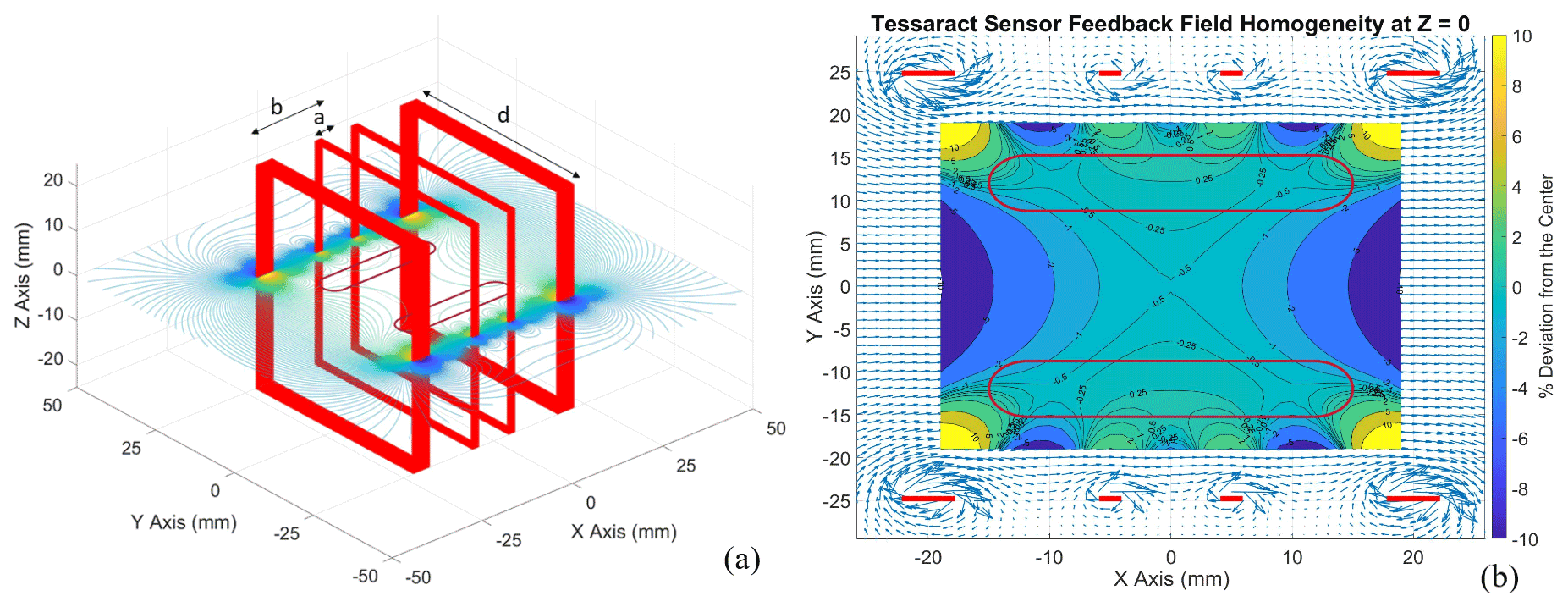
Figure 4(a) A four-square Merritt coil system is the basis of the design for the Tesseract sensor's feedback windings. A Biot–Savart simulation of Tesseract's feedback winding models each loop of wire as a square array assigned a position on a 3D grid. Here we show a rendering of the x axis feedback coil. (b) A 2D cross section at z=0 of the Biot–Savart model of the Tesseract sensor. The maroon loops outline the regions where the racetrack sensors are situated. The contours plot the percentage of deviation of the field from its average along the axis of the racetrack cores ( mm, −12 mm). In this region, the maximum deviation of the magnetic field from the average field along the racetrack core is about 0.42 %. Blue arrows map out the direction and magnitude of the B field, while the red dots represent the positions of the wires.
The simulation of the Tesseract sensor's feedback design suggests that the deviation from a uniform magnetic field along the 1D axis of the racetrack core (at mm) does not exceed 0.45 % (Fig. 4b). We surmise that keeping Tesseract's racetrack cores immersed in this highly magnetically homogeneous region will contribute more stable, linear fluxgate performance.
In this simulation, each loop of wire in the Merritt coil is modeled as a square array with an assigned length, current, and location on a 3D grid (Fig. 4a). A Biot–Savart integration is applied over each element in the square array to evaluate the magnetic field at every point on this grid. This process is repeated for every loop in the coil system, and the resulting field values are summed to create a model of the total magnetic field generated by a Merritt coil system.
2.3.2 Feedback winding optimization
Merritt et al. (1983) provide a natural starting place for constraining the possible positions of the wires. The classic four-square Merritt coil design, rendered in Fig. 4a, groups wires into four “channels”, two outer channels and two inner channels, and places constraints on the size and position of each channel. The distance of the outer channel b and inner channel a from the center (labeled at the top of Fig. 4a) must be related to the length of the coil d, such that and . Additionally, the ideal Merritt coil geometry places constraints on the number of wire turns in each channel. For example, the number of wire turns in the inner channel must be 0.4235 times the number of turns in the outer channel (Merritt et al., 1983).
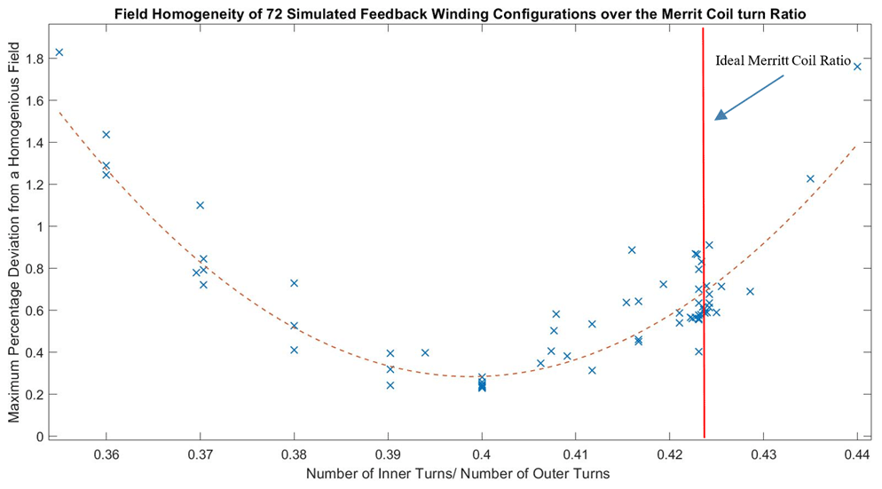
Figure 5The percentage that the field along the racetrack core axis (at y=12 mm, between x=15.7 and −15.7 mm) deviates from the average plotted against the ratio of inner loops of wire to outer loops. Seventy-two feedback winding configurations were simulated using the Biot–Savart model. The results of the simulation showed a relationship between the ratio of inner turns to outer turns and the homogeneity of the magnetic field. A quadratic fit with an R2 value of 0.8 suggests that an inner- to outer-turn ratio of 0.3985 is optimal for homogeneity.
However, given the physical constraints of manufacturing a three-axis sensor, it is necessary to violate these ratios slightly. The requirement for channel spacing must be broken such that in order to maintain three-axis symmetry and the mechanical integrity of the Torlon. Other considerations about the winding (i.e., that the number of layers must be even to ensure that the terminating leads start and end in the same place so that they can be terminated in a twisted pair) place further restrictions on the model. When all these constraints are applied, we are left with the wire gauge, the number of wire turns, and the ratio of the number of inner loops to outer loops as parameters that can vary. The Biot–Savart model (Fig. 4b) was used to simulate 72 possible feedback winding configurations, and the results were analyzed to determine which feedback winding characteristics were optimal for generating a homogenous field along the axis of the racetrack cores.
The field homogeneity generated by a feedback winding was found to have a dependence on that winding's ratio of inner loops to outer loops. Figure 5 plots the percentage that the field at the racetrack core deviates from uniformity against the ratio of inner loops of wire to outer loops. A quadratic fit suggests that an inner- to outer-loop ratio of 0.3985 is optimal for homogeneity. This differs from the classic Merritt coil ratio of 0.4236. Shifting the inner- to outer-loop ratio compensates for the earlier violation of the channel distance requirements for defined in Sect. 2.3.1 that were necessary to construct a physical sensor. Other parameters (wire gauge and total number of wire loops of the feedback winding) were not found to have a discernable correlation with the homogeneity of the feedback magnetic field.
In addition to feedback field homogeneity, another important consideration in selecting an optimal feedback configuration for a magnetospheric sensor is the power dissipation required for these feedback windings to the null maximum earth field ∼ 65 000 nT. This power consumption per axis was calculated using the equation from Magdaleno-Adame et al. (2010):
where N is the total number of turns of wire, d is the length of one side of the square coil (as demarcated in Fig. 4), and, for our purposes, V=5 volts (the maximum voltage allowed by the operational amplifier) and B = 65 000 nT (the maximum field experienced in orbit). This equation implies an inverse relationship between feedback power consumption at earth field Pmax and the total number of loops of wire N. Thus, a feedback configuration with more loops of wire will require less power to null the earth field with an upper limit on the resistance of the coil of to ensure it can null the full field.
Of these 72 simulated feedback winding configurations, 3 were determined to be excellent candidates for good feedback homogeneity and power efficiency. Figure 6 shows the parameters of these configurations along with the modeled magnetic flux density distribution along the axis of the racetrack core for each of these optimized feedback configurations. Prototype no. 1 was the lowest power consumption configuration. Prototype no. 2 was the lowest inhomogeneity, and Prototype no. 3 was chosen for a balance of low inhomogeneity and low power consumption.
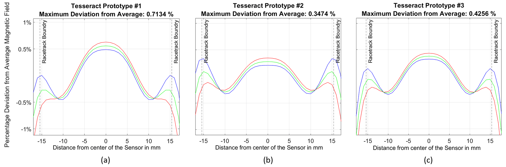
Figure 6Homogeneity of the feedback magnetic field along the axis of the racetrack core for each axis of the three optimized sensors. The racetrack core occupies the region between the vertical dashed black lines at −15.7 and 15.7 mm. Configuration (b) was optimized for best homogeneity, while sensor (c) was chosen for good homogeneity with very low power consumption.
The configuration in Fig. 6c with 864 turns and a wire gauge of 40 AWG was determined to be a suitable balance of good homogeneity and feedback power efficiency. The magnetic field along the racetrack core axis varies by less than 0.46 % on the x axis, 0.38 % on the y axis, and 0.32 % on the z axis. This design requires a sensor power consumption of 89.1 mW to compensate for a worst-case earth field of 65 000 nT, which is very reasonable for accommodation on a small satellite. This is the feedback winding design that we plan to implement on the flight-ready Tesseract magnetometer that will be flown on the ACES-II sounding rockets and again on the TRACERS satellite's mission.
The Tesseract sensor design was prototyped and subjected to a series of tests in order to evaluate the validity of our design models and to quantitatively characterize the sensor's performance. First, several prototype sensors were manufactured and tested for feedback winding homogeneity and stability over temperature. From the results of these initial tests, as described in this section, we selected the prototype that exhibited the most homogeneous feedback field.
Then, a high-fidelity prototype was manufactured with the specifications shown in Table 1. A series of tests was conducted on this prototype to quantify the characteristics of the Tesseract sensor: the feedback field uniformity, the sensitivity and orthogonality over changes in temperature, and the noise floor of the core. All the tests described in this section were conducted at the University of Iowa Magnetometer Calibration Facility.
3.1 Feedback field homogeneity
In order to experimentally characterize the magnetic field generated by the feedback windings and test the results of the Biot–Savart model, three prototype sensors were manufactured with the optimized feedback winding configurations modeled in Fig. 6. For our purposes, we are most interested in quantifying the homogeneity of the feedback magnetic field along the axis of the racetrack core. Each prototype sensor was placed within a single-axis solenoid within a three-layer Mumetal magnetic shield, and a constant current of 20 mA was applied to the feedback windings, creating a magnetic field of about 190 000 nT. A direct-current hall effect milligauss meter probe was placed in the center of the racetrack core's rectangular borehole in the prototype bobbin, and measurements of the magnetic field generated by this current were taken along the bore axis at 2.5 mm intervals. The final value for each measurement was found as an average of that value over four separate tests. The uncertainty was determined by the range over which each measured magnetic field value varied over the four tests. Figure 7 plots the measured magnetic flux distribution along the longest axis of the racetrack core for each prototype sensor as a percentage deviation from the average field value along the borehole axis between −15.7 and 15.7 mm (the domain of the racetrack core).
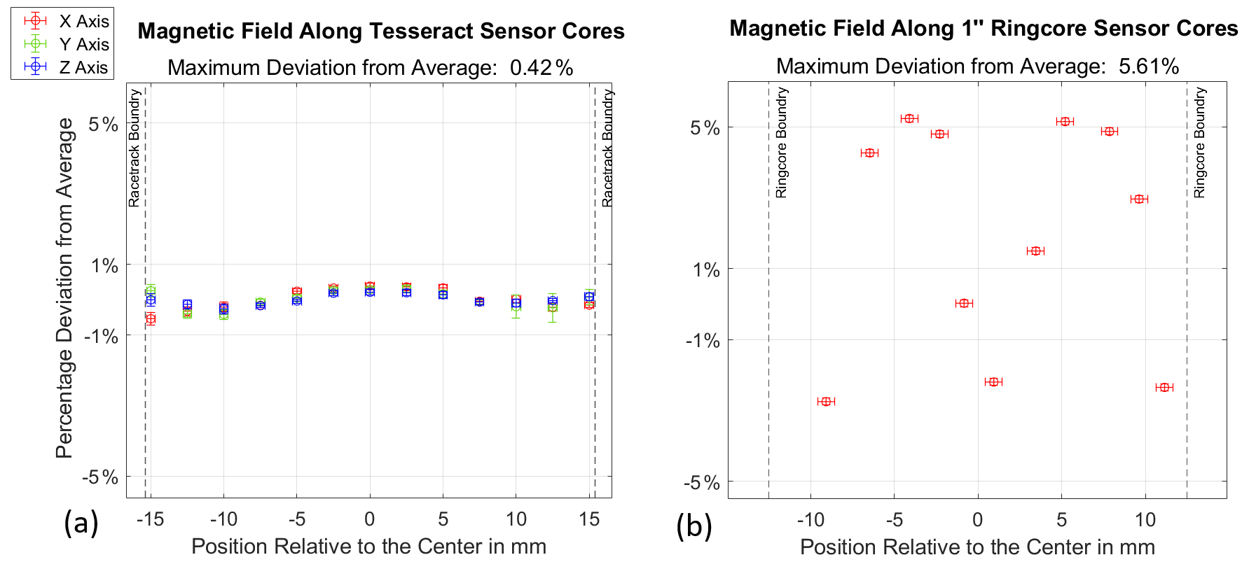
Figure 7(a) The magnetic field generated by the Tesseract Prototype no. 3 sensors' feedback windings was measured in 2.5 mm intervals along the axis of the racetrack borehole. The magnetic field is plotted as the percentage deviation from the average value in the racetrack core region (between −15.7 and 15.7 mm). The feedback magnetic field does not deviate by more than 0.42 % along the core axis, and the feedback coils consume 29.7 mW to the null earth field. (b) The measured percentage deviation of the magnetic field for each position along the axis of the Miles et al. (2013) ring-core sensor feedback winding. The magnetic field deviates by as much as 5.62 % in the domain of the one-inch ring core (between −12.7 and 12.7 mm).
3.1.1 Comparison with the Miles et al. (2013) ring-core sensor feedback field
We performed the same test again, this time using our prototype feedback winding for the Miles et al. (2013) one-inch ring-core sensor (Fig. 1b), which has a similar geometry to its e-POP design (Wallis et al., 2015) and historical missions (e.g., Acuña and Ness, 1980). This ring-core sensor uses solenoidal windings which have similar dimensions for all three axes, so we expect the feedback field to be roughly the same for each axis. Figure 9 plots the measured magnetic flux distribution along the radial axis of the ring core as a percentage deviation from the average field value in this region. Distance is measured from the center of the ring core, and the ring core itself extends from 12.7 to −12.7 mm.
The maximum that the measured feedback field deviates from uniformity along the x axis of the Miles et al. (2013) ring-core sensor is 5.62 %. The Miles et al. (2013) sensor's feedback windings generate a field along the center axis of the ring core that is 10 times more inhomogeneous than that generated by the Tesseract sensor.
3.1.2 Comparison with the Biot–Savart model
The feedback configuration of Prototype 3 (Fig. 7c), with 864 turns of 40 AWG wire on each axis, was chosen to be the current high-fidelity sensor (Fig. 1a) and will be flown on future missions. This feedback winding generates a magnetic field along the axis of its cores that deviates from the average by a maximum of 0.42 % on the x axis, 0.39 % on the y axis, and 0.26 % on the z axis. To assess the effectiveness of our Biot–Savart simulation experimentally, we directly compared these data with the model output for the field values along the axis of the racetrack borehole. The results of the model are plotted for each axis as solid lines (Fig. 8).
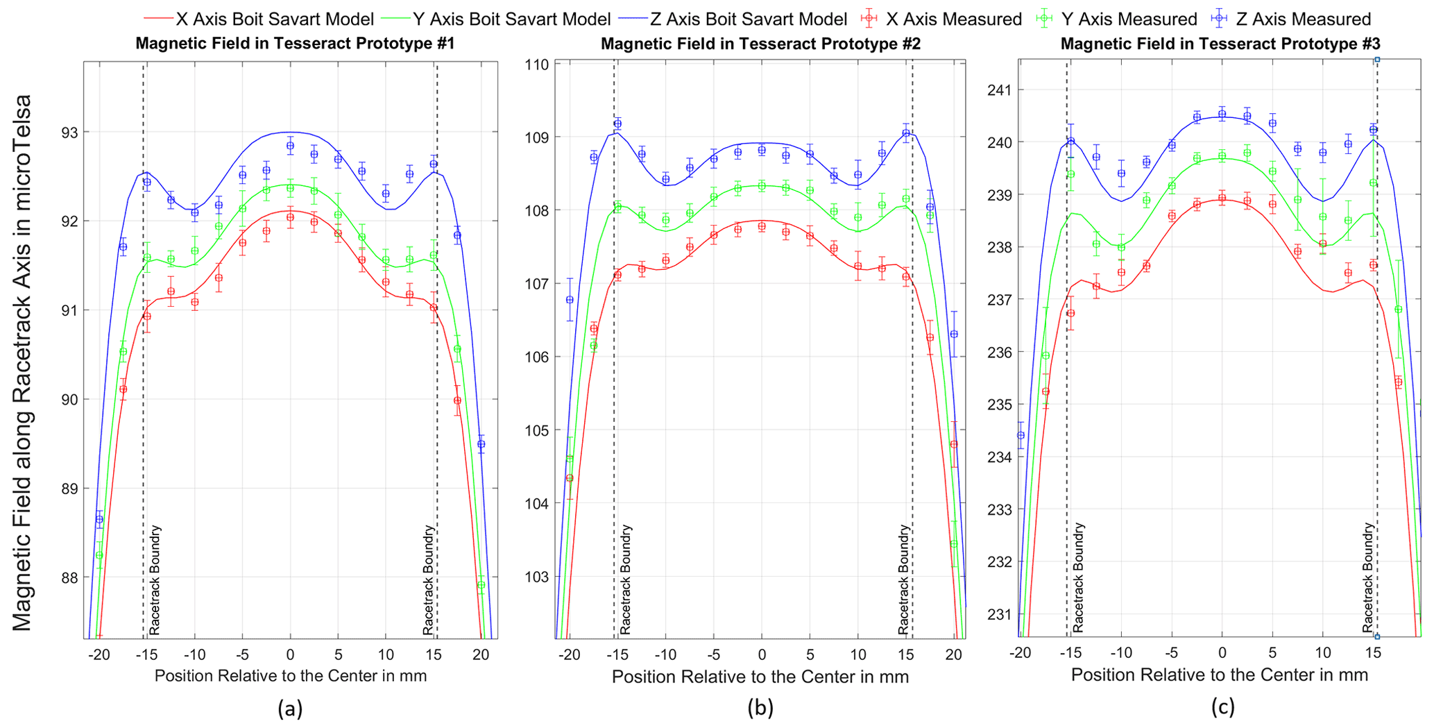
Figure 8The measured values of the magnetic field for each position along the axis of the racetrack borehole are plotted as circles with their corresponding error bars. The output Biot–Savart simulation at the location of the racetrack core is plotted as a solid line.
Slight differences between the field on the three axes are due to Tesseract's differently sized feedback loops that are necessary to nest the physical coils (Fig. 1a). The simulation does a reasonable job of modeling the data within the error bars. To quantify the goodness of the model's fit to the data, the square root of the variance of the residuals (RMSE) and the adjusted R2 values were calculated for each axis and for each of the three prototypes. The Biot–Savart model fits the data to well above an adjusted R2 value of 0.95 and an RMSE below 5.0 for each axis of each prototype sensor. The quality of these fits implies a very strong agreement between the data and the model, and we take this as an experimental validation of our Biot–Savart simulation.
3.2 Sensor stability over temperature
One of the main causes of fluxgate instability is the tendency of a sensor's intrinsic calibration parameters to change due to thermal variations in the sensor's base and feedback windings (Acuña et al., 1978). The fluxgate sensor's sensitivity and orthogonality have long been known to vary with sensor temperature (Trigg et al., 1971). Thus, a characterization of the sensor's sensitivity and orthogonality over the temperature range that would be expected on a magnetospheric or planetary mission is critical for the validation of a space-based fluxgate sensor.
The dominant effect of changes in temperature on a three-axis null sensor is the change in sensitivity due to variations in the geometry of the coils of wire used to provide magnetic feedback (Primdahl and Jensen, 1982), which is in turn dependent on the rate of thermal expansion or contraction of the material of the bobbin upon which the feedback coils are wound (Acuña et al., 1978). The temperature-dependent sensitivity can be corrected to first order by fluxgate electronics using a compensated feedback current (Primdahl, 1970; Acuña et al., 1978; Miles et al., 2017). Another cause of instability is the tendency of the sensor's three orthogonal feedback coils to skew over changes in sensor temperature (Ripka, 1992); however, no equivalent compensation exists for orthogonality, so while smaller temperature-dependent sensitivity is desirable, smaller orthogonality dependence is more critical. Here, we describe a test to measure the sensitivity and orthogonality of the Tesseract sensor's feedback windings over temperature by temporarily configuring it as an air-core search coil magnetometer. This allows us to assess the temperature stability of the sensor base and feedback windings without any dependence on cores or electronics.
3.2.1 Experimental apparatus
Accurately measuring sensitivity and orthogonality over temperature is notoriously challenging, notably due to the difficulty in keeping the excitation/calibration coils thermally isolated from the sensor to ensure that measured changes result from the sensor under test rather than changes in the experimental apparatus. This test usually requires sophisticated equipment. Simpler, low-cost experimental setups have been created (i.e., Brauer et al., 1999; Miles et al., 2017) to calibrate a magnetometer using an insulated cooler filled with dry ice placed within some form of calibration coil.
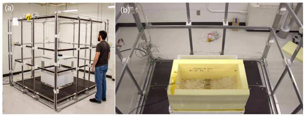
Figure 9(a) The Tesseract prototype is secured in the center of a 2 m Merritt coil system. This coil system is used to generate a field against which Tesseract can be calibrated. (b) The sensor is secured inside a polystyrene box, and the box is filled with dry ice and a Styrofoam lid is placed on top.
To characterize the thermal stability of the Tesseract sensor's base and feedback windings without any dependence on cores and electronics, we temporarily configured it as an air-core search coil magnetometer. The sensor is placed in a thermally insulated box made from 10 cm-thick polystyrene to create a controlled temperature environment for the sensor. The polystyrene box is then placed within the 2 m Merritt coil system shown in Fig. 9a. The Tesseract sensor's axes are manually aligned with the coil system's axes (Fig. 9b) and then slowly rotated until the measured 23 Hz signal is maximized on each axis. The sensor base is then firmly fastened to a mount so that it does not rotate over the course of the test. The coil system is used to generate a 60 000 nT, alternating-current magnetic field at 23 Hz on the x axis for 2 min. The same field is then applied to the y and z axes, and the coil system is set to cycle through x, y, and z, so that a complete measurement of sensitivity and orthogonality is taken every 6 min. A reference vector magnetometer is placed outside of the box, aligned with the coil system, and wrapped in insulating material to monitor the applied alternating-current field and to ensure that the magnitude does not vary.
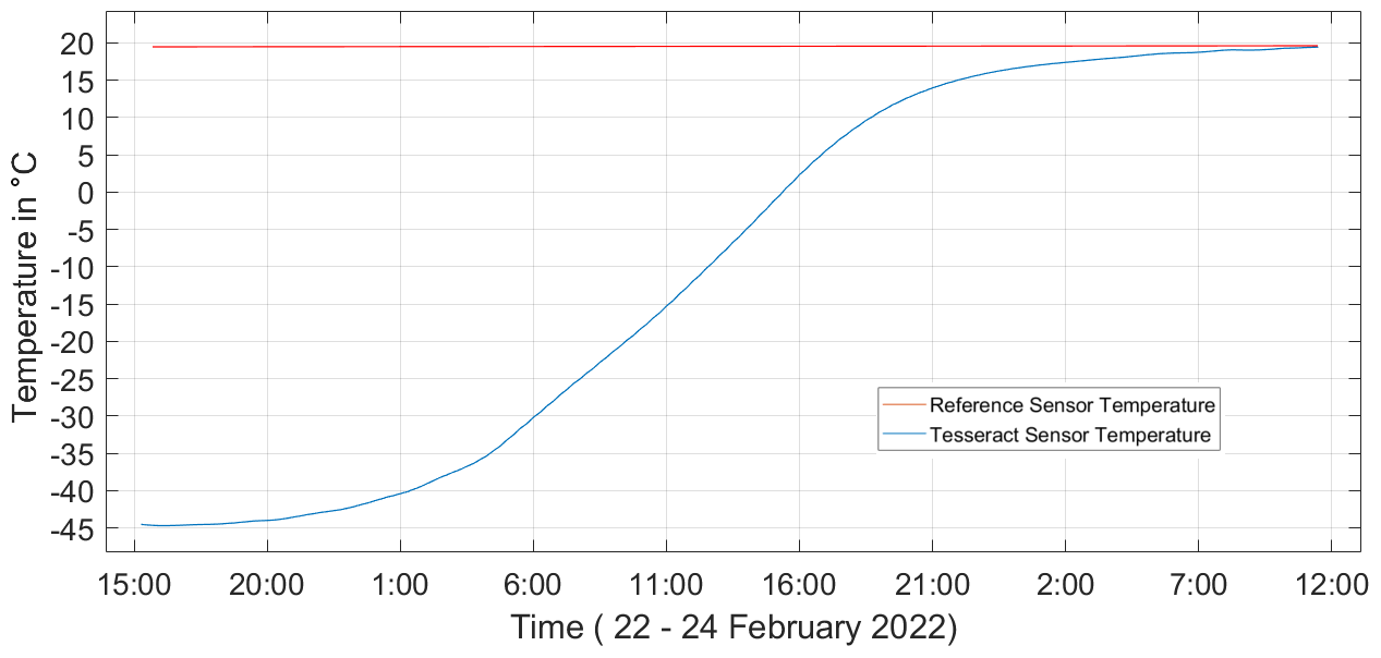
Figure 10The temperature of the Tesseract sensor (blue) is measured using a platinum RTD as the dry ice sublimates. The temperature of the reference magnetometer (red) was also monitored and found to vary by less than 0.1 ∘C over the course of the test.
Five kilograms of dry ice is placed inside the box to chill the sensor, and measurements are taken after the dry ice has sublimated and the sensor is slowly warming. A platinum RTD temperature sensor is attached to the sensor and records the change in temperature as the sensor returns to room temperature (Fig. 10). As the Tesseract sensor temperature slowly increases, the voltage induced in the Tesseract prototype sensor's feedback windings, the reference magnetometer, and the temperature sensors is digitized and recorded using a common 18-bit National Instruments Data Acquisition Device.
3.2.2 Feedback sensitivity and orthogonality over temperature
To evaluate the feedback sensitivity and orthogonality, a finite Fourier transform is performed for each 2 min segment of data where the 23 Hz field is applied to x, then y, and then z. The measured amplitudes of these signals at 23 Hz are recorded for all three axes. This yields nine values that define the calibration of the sensor.
The sensitivity or gain on each axis is simply the output of the feedback winding when the 60 000 nT field is applied in that direction. Figure 12a plots the measured change in sensitivity measured in the x, y, and z feedback windings in parts per million over changes in temperature. The Tesseract sensor's three orthogonality angles, u1, u2, and u3, as defined in Olsen et al. (2003), can be found using simple trigonometry:
where Yy is the field measured on the y axis when the coil system applies a field in y, Zx is the field measured in x when a field is applied in z, and Zy is the field measured in y when a field is applied in z. A is the total magnitude of the applied field, which is defined as , where Xx is the field measured on the x axis when the coil system applies a field on the x axis, Yy is the field measured on the y axis when the coil system applies a field to the y axis, and Zz is the measured field on the z axis when the coil system applies a field to the z axis. Figure 12b plots the change in these angles, u1, u2, and u3, over temperature.
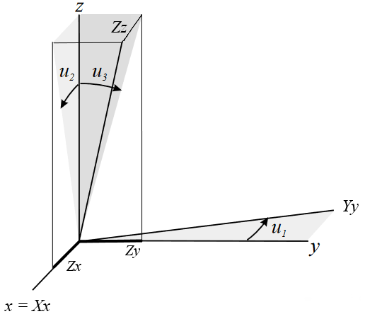
Figure 11The orthogonality angles are defined according to the convention from Olsen et al. (2003). Equations (2), (3), and (4) are different for u1 because the Olsen et al. (2003) convention defines the x axis as projection-invariant, the y axis has a single degree of freedom on the x−y plane, and the z axis has 2 degrees of freedom.
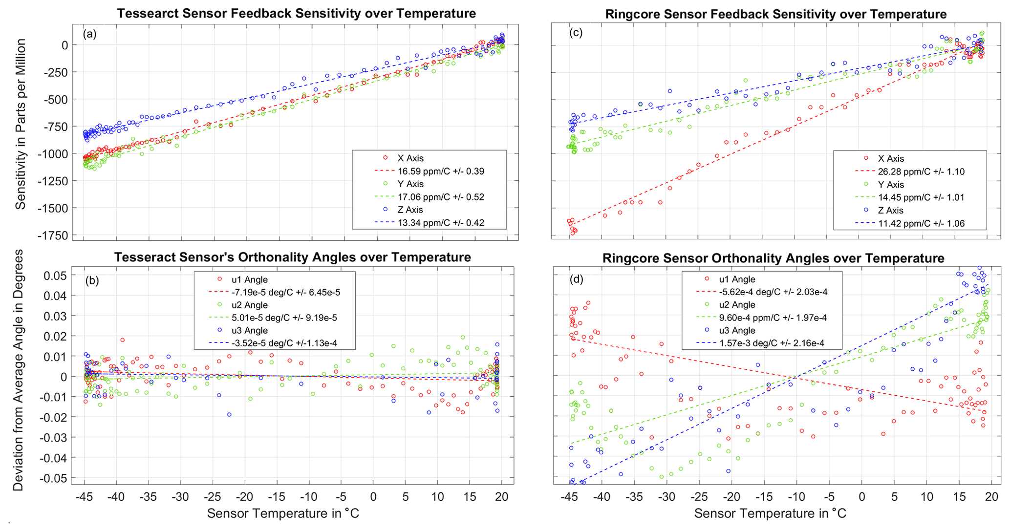
Figure 12(a) The measured sensitivity of the Tesseract sensor's three feedback windings plotted against temperature. Each circle is a 2 min measurement of the amplitude of the 60 000 nT, 23 Hz signal. The dotted lines are a robust linear fit to the data. The fits estimate the Tesseract sensitivity over temperature. (b) The Tesseract sensor's three orthogonality angles, u1, u2, and u3, plotted as a function of sensor temperature. None of the angles are found to unambiguously skew by more than 0.015∘. (c) The measured sensitivity of the Miles et al. (2013) ring-core sensor's three feedback windings plotted against temperature. (d) The Miles et al. (2013) ring-core sensors' orthogonality angles are found to skew over temperature by as much as 0.09∘.
Notwithstanding this modest experimental setup, we are able to measure the sensor's change in sensitivity and orthogonality over temperature. A robust linear fit to the data gives an estimate of the linear dependence of sensitivity on temperature. On all three axes, the sensitivities to temperature are very linear, with R2 values of 0.995. We expect that this will make temperature compensation very effective, since the compensation method used by Acuña et al. (1978) is strictly linear. The sensitivity to temperature on the x and y axes is 16.6 and 17.1 ppm ∘C−1, respectively, very comparable to the thermal coefficient of expansion of copper (16.7 ppm ∘C−1) and of the Torlon base material (16.2 ppm ∘C−1), as predicted by Acuña et al. (1978). The z axis, which is aligned with the direction that Torlon extrusion was injected into the mold during manufacturing, differs slightly (13.3 ppm ∘C−1). Over the course of the test, the signal measured by the reference magnetometer does not vary by more than 20 ppm on each axis, which confirms that these changes in sensitivity are due to changes in the sensor's feedback windings and not the applied field.
We do not measure any variation in axis alignment to within deviations of 0.015∘ over changes in temperature from −45 to 20 ∘C. The sensor's feedback windings are a less-than-ideal search coil, so the accuracy of the measurements is limited by a poor signal. The background magnetic noise of the laboratory also limits the accuracy of this test. This test will be repeated once the sensor is integrated into a functioning fluxgate instrument in a magnetically quiet facility in order to verify its flight calibrations.
3.2.3 Comparison with the Miles et al. (2013) ring-core sensor design
The sensitivity and orthogonality of the ring-core's feedback windings over temperature were measured with the same method described above. The Miles et al. (2013) ring-core sensor design (Fig. 1b) was also temporarily configured as an air-core search coil magnetometer so that attributes of the sensor base and feedback windings could be directly measured. The measured sensitivity and orthogonality over temperature are plotted in Fig. 12b and d.
While the Tesseract and ring-core sensors have comparable thermal sensitivities, Tesseract's sensitivity over temperature is more consistent on each axis, presumably due to the greater symmetry of the sensor's feedback windings. The ring-core sensors' orthogonality angles skew by as much as 0.09∘ (Fig. 12d). The u3 angle (blue) changes the most, presumably because the Miles et al. (2013) ring-core sensor base is most asymmetric between the y and z axes (Fig. 1b).
3.3 Sensor noise
The noise floor of a fluxgate is typically limited by the intrinsic magnetic noise of a ferromagnetic core that is periodically driven into magnetic saturation to modulate the local magnetic field. The noise floor on Tesseract's custom miniature racetrack cores was characterized in Miles et al. (2022). A single-axis electronics board was used to drive and sample each fluxgate core. The power spectral density noise floor of the instrument was estimated by using 20 min of data, while the racetrack sensors were inside a single-axis four-layer Mumetal magnetic shield. The noise floors for the racetrack core sensors that will be used in Tesseract were determined to be 5 pT √Hz−1 at 1 Hz (Miles et al., 2022).
The novel fluxgate sensor called Tesseract has been designed and prototyped. It is a low-mass, low-noise sensor that mitigates several known causes of instability in our one-inch ring-core design. We modeled the sensor's feedback winding using a Biot–Savart simulation and used it to optimize the Tesseract sensor's feedback topology for homogeneity and power consumption. The simulation results were in agreement with laboratory measurements of the prototype sensors' feedback magnetic field. Tesseract retains its ferromagnetic cores in a feedback magnetic field that is homogeneous to within deviations of 0.42 %.
We used a low-cost method to analyze the sensitivity and orthogonality of the sensor over temperature independent of cores or electronics. Using this method, we show that Tesseract's three orthogonal axes skew by no more than 0.015∘ over changes in temperature from −45 to 20 ∘C. The Tesseract sensor outperforms our one-inch ring-core sensor design in both these metrics. Tesseract's orthogonal axes are more stable by at least a factor of 4, and its magnetic feedback is more homogenous by a factor of 13. We surmise that the Tesseract sensor's higher degree of feedback homogeneity and axis stability over temperature will contribute to improved fluxgate stability.
4.1 Future work
The accuracy of these measurements is limited by the magnetic noise of the laboratory setup, and in an uncontrolled warming there is always the possibility of thermal gradients or transients. A more sophisticated experimental setup will be required to characterize the stability of Tesseract's calibration parameters to an accuracy acceptable for most space science applications (greater than ±0.1 nT). We are currently developing a new calibration facility at the University of Iowa that will be purpose-built for controlled temperature characterization of fluxgate sensor calibration parameters, which will incorporate better shielding and limit the possibility of thermal gradients or shocks. In future studies, we hope to use the specialized, environmentally controlled Helmholtz coil facility at Goddard Space Flight Center that would be capable of resolving Tesseract's long-term stability to a precision of ±200 pT (Vernier et al., 2004).
Fluxgate electronics are currently being developed for the Tesseract sensor in preparation for upcoming flights. Once the sensor has been integrated with cores and electronics, Tesseract will be characterized again as a complete flight-ready fluxgate instrument. Tesseract will be flight-demonstrated on the ACES-II sounding rockets, currently scheduled to launch in December 2022, and again aboard the TRACERS satellite mission as part of the MAGIC technology demonstration which is scheduled to launch in 2023.
Data and source code used in the creation of this paper can be accessed by contacting the authors.
KG led the design, assembly, and execution of the experiments, analyzed the data, created the feedback field simulation, and wrote the manuscript with contributions from all the authors. DMM provided supervision and funding of the project as the lead investigator and assisted in the interpretation of the data. CH led the development and manufacture of the Tesseract sensor prototypes. BBN conceptualized the Tesseract sensor design. RD assisted with the design of the sensor prototypes and testing apparatus.
B. Barry Narod operated Narod Geophysics Ltd., which manufactured fluxgate magnetometers until the company ceased production operation in 2008.
Publisher’s note: Copernicus Publications remains neutral with regard to jurisdictional claims in published maps and institutional affiliations.
The authors are greatly indebted to Suman Sherwani and Amanda Lasko. This work would not have been possible if it were not for their oversight and management of the prototype manufacturing and testing processes. Special thanks to Samuel Hisel, Antonio Washington, and Alex Hoffman for lending their expertise to laboratory electronics and software and for their flexibility in managing hardware that made this experimental work feasible. Special thanks to Michael D. Webb for lending his expertise to laboratory equipment. The authors would also like to thank Steve Klinkhammer and Ryan Helland for their manufacturing efforts and Katherine Deasy for her work in configuration management.
Early development activities and much of the research infrastructure used in this work were supported by faculty start-up funding for David Miles from the University of Iowa. This material is based upon work supported by the National Aeronautics and Space Administration under grant no. 80NSSC19K0491 issued through the Science Mission Directorate and contract no. 80GSFC18C0008 administered by Goddard Space Flight Center.
This research has been supported by the National Aeronautics and Space Administration (grant no. 80NSSC19K0491).
This paper was edited by Valery Korepanov and reviewed by Mark Moldwin, Hans-Ulrich Auster, and one anonymous referee.
Acuña, M. H. and Ness, N. F.: The Magnetic Field of Saturn: Pioneer 11 Observations, Science, 207, 444–446, https://doi.org/10.1126/science.207.4429.444, 1980.
Acuña, M. H., Scearce, C. S., Seek, J., and Scheifele, J.: The MAGSAT vector magnetometer: A precision fluxgate magnetometer for the measurement of the geomagnetic field, Technical report, National Aeronautics and Space Administration, Goddard Space Flight Center, Greenbelt, Maryland, 1978.
Auster, H. U., Glassmeier, K. H., Magnes, W., Aydogar, O., Baumjohann, W., Constantinescu, D., Fischer, D., Fornacon, K. H., Georgescu, E., Harvey, P., Hillenmaier, O., Kroth, R., Ludlam, M., Narita, Y., Nakamura, R., Okrafka, K., Plaschke, F., Richter, I., Schwarzl, H., Stoll, B., Valavanoglou, A., and Wiedemann, M.: The THEMIS Fluxgate Magnetometer, Space Sci. Rev., 141, 235–264, https://doi.org/10.1007/s11214-008-9365-9, 2008.
Balogh, A., Carr, C. M., Acuña, M. H., Dunlop, M. W., Beek, T. J., Brown, P., Fornacon, K.-H., Georgescu, E., Glassmeier, K.-H., Harris, J., Musmann, G., Oddy, T., and Schwingenschuh, K.: The Cluster Magnetic Field Investigation: overview of in-flight performance and initial results, Ann. Geophys., 19, 1207–1217, https://doi.org/10.5194/angeo-19-1207-2001, 2001.
Bandyopadhyay, S., Subramanian, G. P., Foust, R., Morgan, D., Chung, S.-J., and Hadaegh, F.: A Review of Impending Small Satellite Formation Flying Missions, in: 53rd AIAA Aerospace Sciences Meeting, 53rd AIAA Aerospace Sciences Meeting, Kissimmee, Florida, https://doi.org/10.2514/6.2015-1623, 2015.
Brauer, P., Merayo, J. M. G., Nielsen, O. V., Primdahl, F., and Petersen, J. R.: Transverse field effect in fluxgate sensors, Sensor. Actuat. A-Phys., 59, 70–74, https://doi.org/10.1016/S0924-4247(97)01416-7, 1997.
Brauer, P., Merayo, J. M. G., Risbo, T., and Primdahl, F.: Magnetic calibration of vector magnetometers, in: Workshop on Calibration of Space-Borne Magnetometers, Institute of Geophysics and Meteorology, Technical University of Braunschweig, 1999.
Chulliat, A., Savary, J., Telali, A., and Lalanne, X.: Acquisition of 1-Second Data in IPGP Magnetic Observatories, Proceedings of the XIIIth IAGA Workshop on Geomagnetic Observatory Instruments, Data Acquisition, and Processing, U.S. Geological Survey Open-File Report 2009–1226, 54–59, 2009.
Forslund, Å., Belyayev, S., Ivchenko, N., Olsson, G., Edberg, T., and Marusenkov, A.: Miniaturized digital fluxgate magnetometer for small spacecraft applications, Meas. Sci. Technol., 19, 015202, https://doi.org/10.1088/0957-0233/19/1/015202, 2008.
Ganushkina, N., Jaynes, A., and Liemohn, M.: Space Weather Effects Produced by the Ring Current Particles, Space Sci. Rev., 212, 1315–1344, https://doi.org/10.1007/s11214-017-0412-2, 2017.
Garrick-Bethell, I., Paige, D. A., Burton, M., Boland, J., Abrahams, J. N. H., Bogert, C. van der, Choi, Y.-J., Deca, J., Hanna, K. D., Farrell, W. M., Hemingway, D., Hiesinger, H., Jin, H., Johnson, B. C., Kaluna, H., Kelley, M. R., Larson, D. E., Lawrence, D. J., Li, S., Ma, Y., Maxwell, R. E., Miller, R. S., Pieters, C. M., Poppe, A. R., Ravat, D., Russell, C. T., Siegler, M. A., Vernazza, P., and Weiss, B. P.: NanoSWARM: NanoSatellites for Space Weathering, Surface Water, Solar Wind, and Remanent Magnetism, BAAS, 53, 354, https://doi.org/10.3847/25c2cfeb.314447c9, 2021.
Janosek, M.: Parallel fluxgate magnetometers, in: High Sensitivity Magnetometers, edited by: Grosz, A., Haji-Sheikh, M., and Mukhopadhyay, S., Springer, Cham, Vol. 19, https://doi.org/10.1007/978-3-319-34070-8_2, 2017.
Kepko, L., Clagett, C., Santos, L., Azimi, B., Berry, D., Bonalsky, T., Chai, D., Cudmore, A., Evans, A., Hesh, S., Jones, S., Marshall, J., Paschalidis, N., Rodriquez, J., Rodriquez, M., Sheikh, S., Starin, S., and Zesta, E.: Dellingr: NASA Goddard Space Flight Center's First 6U Spacecraft, 12, 2017.
Korepanov, V. and Marusenkov, A.: Flux-Gate Magnetometers Design Peculiarities, Surv. Geophys., 33, 1059–1079, https://doi.org/10.1007/s10712-012-9197-8, 2012.
Magdaleno-Adame, S., Olivares-Galvan, J. C., Campero-Littlewood, E., Escarela-Perez, R., and Blanco-Brisset, E.: COSMOL Conference, Boston, USA, 5 July, Coil Systems to Generate Uniform Magnetic Field Volumes, 7, 2010.
Maruca, B. A., Agudelo Rueda, J. A., Bandyopadhyay, R., Bianco, F. B., Chasapis, A., Chhiber, R., DeWeese, H., Matthaeus, W. H., Miles, D. M., Qudsi, R. A., Richardson, M. J., Servidio, S., Shay, M. A., Sundkvist, D., Verscharen, D., Vines, S. K., Westlake, J. H., and Wicks, R. T.: MagneToRE: Mapping the 3-D Magnetic Structure of the Solar Wind Using a Large Constellation of Nanosatellites, Front. Astron. Space Sci., 8, 665885, https://doi.org/10.3389/fspas.2021.665885, 2021.
Merayo, J. M. G., Jørgensen, J. L., Friis-Christensen, E., Brauer, P., Primdahl, F., Jørgensen, P. S., Allin, T. H., and Denver, T.: The Swarm magnetometry package, InSmall satellites for Earth observation, 143–151, Springer, Dordrecht, https://doi.org/10.1007/978-1-4020-6943-7_13, 2008.
Merritt, R., Purcell, C., and Stroink, G.: Uniform magnetic field produced by three, four, and five square coils, Rev. Sci. Instrum., 54, 879–882, https://doi.org/10.1063/1.1137480, 1983.
Miles, D. M., Bennest, J. R., Mann, I. R., and Millling, D. K.: A radiation hardened digital fluxgate magnetometer for space applications, Geosci. Instrum. Method. Data Syst., 2, 213–224, https://doi.org/10.5194/gi-2-213-2013, 2013.
Miles, D. M., Mann, I. R., Ciurzynski, M., Barona, D., Narod, B. B., Bennest, J. R., Pakhotin, I. P., Kale, A., Bruner, B., Nokes, C. D. A., Cupido, C., Haluza-DeLay, T., Elliott, D. G., and Milling, D. K.: A miniature, low-power scientific fluxgate magnetometer: A stepping-stone to cube-satellite constellation missions: A Miniature Fluxgate Magnetometer, J. Geophys. Res.-Space, 121, 11839–11860, https://doi.org/10.1002/2016JA023147, 2016.
Miles, D. M., Mann, I. R., Kale, A., Milling, D. K., Narod, B. B., Bennest, J. R., Barona, D., and Unsworth, M. J.: The effect of winding and core support material on the thermal gain dependence of a fluxgate magnetometer sensor, Geosci. Instrum. Method. Data Syst., 6, 377–396, https://doi.org/10.5194/gi-6-377-2017, 2017.
Miles, D. M., Ciurzynski, M., Barona, D., Narod, B. B., Bennest, J. R., Kale, A., Lessard, M., Milling, D. K., Larson, J., and Mann, I. R.: Low-noise permalloy ring cores for fluxgate magnetometers, Geosci. Instrum. Method. Data Syst., 8, 227–240, https://doi.org/10.5194/gi-8-227-2019, 2019.
Miles, D. M., Dvorsky, R., Greene, K., Hansen, C. T., Narod, B. B., and Webb, M. D.: Contributors to fluxgate magnetic noise in permalloy foils including a potential new copper alloy regime, Geosci. Instrum. Method. Data Syst., 11, 111–126, https://doi.org/10.5194/gi-11-111-2022, 2022.
Moldovanu, A., Chiriac, H., Moldovanu, C., Macoviciuc, M., and Ioan, C.: Performances of the fluxgate sensor with tensile stress annealed ribbons, Sensor. Actuat. A-Phys., 81, 189–192, https://doi.org/10.1016/S0924-4247(99)00085-0, 2000.
Nakariakov, V. M., Pilipenko, V., Heilig, B., Jelínek, P., Karlický, M., Klimushkin, D. Y., Kolotkov, D. Y., Lee, D.-H., Nisticò, G., Van Doorsselaere, T., Verth, G., and Zimovets, I. V.: Magnetohydrodynamic Oscillations in the Solar Corona and Earth's Magnetosphere: Towards Consolidated Understanding, Space Sci. Rev., 200, 75–203, https://doi.org/10.1007/s11214-015-0233-0, 2016.
Narod, B. B. and Bennest, J. R.: Ring-core fluxgate magnetometers for use as observatory variometers, Phys. Earth Planet. In., 59, 23–28, https://doi.org/10.1016/0031-9201(90)90205-C, 1990.
Olsen, N., Tøffner-Clausen, L., Sabaka, T. J., Brauer, P., Merayo, J. M. G., Jørgensen, J. L., Léger, J. M., Nielsen, O. V., Primdahl, F., and Risbo, T.: Calibration of the Ørsted vector magnetometer, Earth Planets Space, 55, 11–18, https://doi.org/10.1186/BF03352458, 2003.
Petrucha, V., Janosek, M., and Azpurua, M. A.: Vector Feedback Homogeneity and Inner Layout Influence on Fluxgate Sensor Parameters, IEEE T. Instrum. Meas., 64, 1285–1291, https://doi.org/10.1109/TIM.2014.2362831, 2015.
Pfaff Jr., R. F.: An Overview of the Scientific and Space Weather Motivation for the Notional Geospace Dynamics Constellation Mission, AGU Fall Conference, San Francisco, CA, 13 December, SA23C-01, 2016.
Primdahl, F.: Temperature compensation of fluxgate magnetometers, IEEE T. Magn., 6, 819–822, https://doi.org/10.1109/TMAG.1970.1066971, 1970.
Primdahl, F.: The fluxgate magnetometer, J. Phys. E Sci. Instrum., 12, 241–253, https://doi.org/10.1088/0022-3735/12/4/001, 1979.
Primdahl, F. and Jensen, P. A.: Compact spherical coil for fluxgate magnetometer vector feedback, J. Phys. E Sci. Instrum., 15, 221–226, https://doi.org/10.1088/0022-3735/15/2/015, 1982.
Ripka, P.: Review of fluxgate sensors, Sensor. Actuat. A-Phys., 33, 129–141, https://doi.org/10.1016/0924-4247(92)80159-Z, 1992.
Ripka, P.: Advances in fluxgate sensors, Sensor. Actuat. A-Phys., 106, 8–14, https://doi.org/10.1016/S0924-4247(03)00094-3, 2003.
Ripka, P. and Billingsley, S. W.: Crossfield effect at fluxgate, Sensor. Actuat. A-Phys., 81, 176–179, https://doi.org/10.1016/S0924-4247(99)00082-5, 2000.
Ripka, P., Pribil, M., and Butta, M.: Fluxgate Offset Study, IEEE T. Magn., 50, 1–4, https://doi.org/10.1109/TMAG.2014.2329777, 2014.
Slavin, J. A., Le, G., Strangeway, R. J., Wang, Y., Boardsen, S. A., Moldwin, M. B., and Spence, H. E.: Space Technology 5 multi-point measurements of near-Earth magnetic fields: Initial results, Geophys. Res. Lett., 35, L02107, https://doi.org/10.1029/2007GL031728, 2008.
Torbert, R. B., Russell, C. T., Magnes, W., Ergun, R. E., Lindqvist, P.-A., LeContel, O., Vaith, H., Macri, J., Myers, S., Rau, D., Needell, J., King, B., Granoff, M., Chutter, M., Dors, I., Olsson, G., Khotyaintsev, Y. V., Eriksson, A., Kletzing, C. A., Bounds, S., Anderson, B., Baumjohann, W., Steller, M., Bromund, K., Le, G., Nakamura, R., Strangeway, R. J., Leinweber, H. K., Tucker, S., Westfall, J., Fischer, D., Plaschke, F., Porter, J., and Lappalainen, K.: The FIELDS Instrument Suite on MMS: Scientific Objectives, Measurements, and Data Products, Space Sci. Rev., 199, 105–135, https://doi.org/10.1007/s11214-014-0109-8, 2016.
Trigg, D. F., Serson, P. H., and Camfield, P. A.: A solid-state electrical recording magnetometer, vol. 41, Publ. Earth Phys. Branch, Dept. Energy, Mines and Resources, Ottawa, 66–80, 1971.
Vernier, R., Bonalsky, T., and Slavin, J.: Goddard space flight center spacecraft magnetic test facility restoration project, 23rd Space Simulation Conference Proceedings, 2004.
Wallis, D. D., Miles, D. M., Narod, B. B., Bennest, J. R., Murphy, K. R., Mann, I. R., and Yau, A. W.: The CASSIOPE/e-POP Magnetic Field Instrument (MGF), Space Sci. Rev., 189, 27–39, https://doi.org/10.1007/s11214-014-0105-z, 2015.