the Creative Commons Attribution 4.0 License.
the Creative Commons Attribution 4.0 License.
 | 13 Feb 2024
An optimized and hybrid gating scheme for the suppression of very low-frequency radios in transient electromagnetic systems
Smith Kashiram Khare
Paul McLachlan
Pradip Kumar Maurya
One of the most widely used approaches for measuring the earth's subsurface resistivity is the transient electromagnetic (TEM) method. However, noise and interference from different sources, e.g., radio communication, the instrument, the atmosphere, and power lines, severely taint these types of signals. In particular, radio transmission in the very low-frequency (VLF) range between 3 and 30 kHz is one of the most prominent sources of noise. Transient electromagnetic signals are normally gated to increase the signal-to-noise ratio. A precise selection of gate shapes is required to suppress undesired noise while allowing the TEM signal to pass unaltered. We employ the multi-objective particle swarm optimization technique to choose optimal gate shapes and placements by minimizing an objective function composed of standard error bars, the covariance between gates, and the distortion of the gated signal. The proposed method is applied to both fully sampled synthetic TEM data and to boxcar-gated field data. The best output from the search space of gate shapes was found to be a hybrid combination of boxcar and Hamming gates. The effectiveness of hybrid gating over traditional boxcar and semi-tapered gating is confirmed by an analysis of covariance matrices and error bars. The results show that the developed method effectively suppresses VLF noise in the middle gates, which are gates with center times spanning 30 to 200 µs , and in the late gates, which are gates with center times spanning 200 to 1130 µs. The analysis shows that the average improvement in standard errors obtained for the hybrid gating scheme over boxcar gating is 1.719 and 1.717 for synthetic and field data, respectively.
- Article
(1898 KB) - Full-text XML
- BibTeX
- EndNote


The transient electromagnetic (TEM) method is a well-known and well-accepted technology utilized in mineral exploration, groundwater mapping, saltwater boundary mapping, and a variety of other applications (Auken et al., 2017; Law et al., 2019; Chen et al., 2020). TEM surveys can be done using ground-based instruments that are moved manually between measurements or instruments mounted on mobile platforms, such as fixed-wing aircraft and helicopters, or towed behind all-terrain vehicles (Mulè et al., 2012; Auken et al., 2019; Liu et al., 2019; Chen et al., 2022). Moving systems are a cost-effective solution with high spatial resolution that allows for large-area mapping. New emerging applications of TEM include permanently installed monitoring instruments that track changes in the groundwater levels through daily measurements. However, such applications greatly increase the need for data with a high signal-to-noise ratio (SNR) as the changes in response caused by temporal groundwater variations are embedded in large background signals (Zamora-Luria et al., 2022).
Multiple noise sources interfere with the TEM signals. The noise sources include power-line noise (50 or 60 Hz) and its harmonics, internal instrumental noise (thermal noise, aging of electronic components, etc.), environmental noise (sferic noise from thunderstorms, traffic, etc.), interference from radio communication systems in the low-frequency (LF, 30–300 kHz) and very low-frequency (VLF, 3–30 kHz) range, and motion noise in the moving systems (Liu et al., 2019; Chen et al., 2022; Macnae et al., 1984; Rasmussen et al., 2018a). Signals from VLF and LF radio communication are one of the most significant sources of noise for TEM systems. The gating of data is one way to reduce the effect of VLF radios in measured TEM data. Gating has traditionally been carried out with analog boxcar integrators, but new fully sampled digital receivers offer more flexibility in the gate design. Many different gate shapes with correspondingly different frequency responses are available. However, careful selection of gate shape and placement is necessary to achieve the minimum VLF noise influence in the gated signal. No standard method or principle is available to suggest a choice of a particular gate shape to suppress the effect of VLF radios. Selecting the right gate shape and position manually is time-consuming and prone to poor performance due to spontaneously or spatially varying environmental conditions and changing strengths of VLF radios.
Hence, this work aims to design an optimum gating scheme that is able to suppress the VLF radios in the gated signal and able to adjust itself regularly, e.g., to track daily changes in noise conditions in monitoring instruments. Its significant contributions are the following:
-
Design and implementation of a fully sampled 4 MHz synthetic model for generating noiseless and noisy TEM signals
-
Design of gate banks with selected gate shapes to be utilized for gating TEM signals from moving or stationary instruments
-
Implementation of a new covariance matrix CM tool for studying the presence of VLF noise in the data
-
Design of a hybrid gate distribution scheme for suppressing the effect of VLF noise in measured TEM signals
-
Optimization of gates by minimizing a multi-objective cost function composed of standard errors of gated data, signal distortion, and covariance
-
Validation of the hybrid gating model with synthetic TEM signals and field data acquired in Denmark with an analog boxcar gating instrument
The remainder of the paper is structured as follows: Sect. 2 provides a background of the TEM system, related work, and motivation. Section 3 provides a detailed discussion and implementation of the proposed model. Details about the experimental setup of the synthetic and towed-TEM model are covered in Sect. 4. The results of the proposed model are discussed in Sect. 5. Finally, conclusions are presented in Sect. 6.
2.1 Background
Briefly, the principles of TEM measurements are as follows (Nabighian and Macnae, 1991) and as shown in Fig. 1. A primary magnetic field is generated by applying an input current pulse to a transmitter coil. The coil is normally laid out on the ground or attached to a moving platform. The current is turned on smoothly and turned off abruptly. Following Lenz's law, eddy currents are induced in the earth below the coil when the primary field is turned off abruptly. The eddy currents produce a secondary magnetic field, which is then measured by a receiver coil (an induction coil). The eddy currents decay and the shape of the decay is controlled by the resistivity of the earth, which can therefore be retrieved from the data. The measured response following a single transmitter pulse is termed a transient. Details of the earth's subsurface resistivity structure are encoded in the secondary magnetic field and can be extracted by an inversion procedure (Nabighian and Macnae, 1991). As seen from Fig. 1, the primary field consists of positive and negative pulses. Sequences of alternating sign pulses are used to mitigate the effect of power-line harmonics and instrument bias by sign correction and stacking of data (Macnae et al., 1984). The resulting TEM signals have a high amplitude and bandwidth in the early times, but both amplitude and bandwidth drop rapidly towards the late times, approximately as , resulting in lower values of the SNR at late times.
The high-frequency content in the early times is captured by selecting short early gate widths, typically on the order of a few microseconds. In comparison, the signals' late-time response and low-frequency content are captured by gates of increasingly longer duration. Gating is the integration of the signal over specified adjacent time windows. Essentially, gating provides a decimation of data, and it corresponds to a filtering of the signal with a filter whose frequency response is obtained by taking the Fourier transform of the gate shape. As a result, gating is critical for signal interpretation and data reduction.
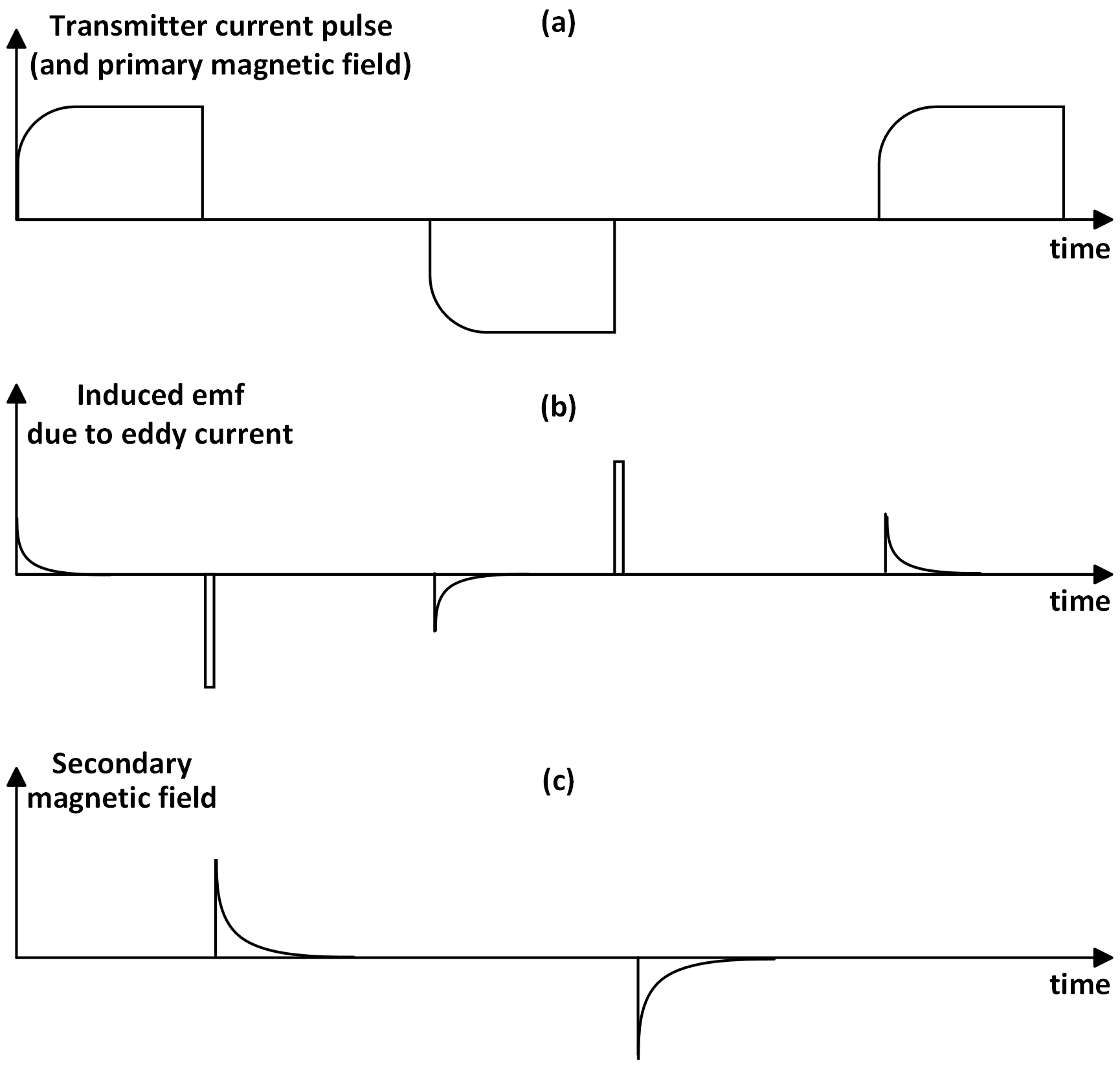
Figure 1Exemplary waveforms of the TEM system: (a) current pulse to transmitter coil, (b) induced electromotive force from an eddy current, and (c) decaying secondary field in the receiver coil.
2.2 Related work
Many studies have been conducted to investigate the properties of VLF radio signals in various fields, including lightning–ionosphere interactions and uncrewed airborne geophysical surveys. To study the effect of lightning on the ionosphere, a technique based on probing sub-ionospheric VLF has been investigated (Inan et al., 2010). VLF measurements using airborne systems have been used for geophysical surveys to investigate ground conductivity (Eppelbaum and Mishne, 2011; Pedersen and Oskooi, 2004). Similarly, VLF signals have also been used for mapping the conductivity of sedimentary cover (Oskooi and Pedersen, 2005). It should be noted that the methods discussed above are concerned with studying or using the effect of VLF radios in measurements rather than suppressing them.
The role of VLF noise in the measurement and analysis of TEM signals is significant. Boxcar gating with a rectangular window using analog integrators has been used widely. However, the frequency response of the boxcar has large side lobes that can let the VLF radios in the measured signal pass through (Harris, 1978). If the TEM instrument allows for acquisition of many short boxcar gates during single transients, semi-tapered gates with improved frequency responses can be formed as linear combinations of the short gates, which leads to improved suppression of VLF radios (Larsen et al., 2021).
New fully sampled digital receiver systems can employ any desired gate shape; e.g., a B-spline-based gating scheme has been explored to compress the measured TEM data in the SkyTEM receiver system (Nyboe and Mai, 2017). The splines are distributed such that at any instant of time, a unity weight is obtained after summing the respective weights of spline coefficients. In a recent paper, the suppression of VLF radios by B-spline gating has been further examined (Peng et al., 2022).
However, the semi-tapered and B-spline-based gating schemes have only used an optimization metric about reducing standard error bars to suppress the effect of VLF radios (Peng et al., 2022; Larsen et al., 2021). Since the standard error bars of the measured data are inversely proportional to the width of the gates, increasing the gate width improves the SNR but does not guarantee suppression of VLF radios. VLF radio signals remain coherent across individual TEM measurements; therefore, mere stacking does not necessarily suppress the underlying VLF radios. In fact, due to coherence between the repeating TEM signals and VLF radio signals, there is a possibility of lower error bars in the measured data after gating, yet VLF radio signals are still present in the data (Larsen et al., 2021; Peng et al., 2022). A subtraction method to remove the VLF radios from measured TEM data has been presented (Macnae, 2015; Rasmussen et al., 2018b). The subtraction method works by identifying the bit streams in the VLF radio signals. The bit streams are then used to generate a copy of the VLF radio signals, which can be subtracted from the received TEM signals. However, this is a computationally expensive method compared to gating. Importantly, only a few papers have been published about suppressing VLF noise in TEM measurements. This suggests that further investigations could potentially lead to improved SNR.
2.3 Motivation
During the late times, from about 100 µs onward, the VLF signals' amplitude dominates the TEM signal's amplitude. Due to the VLF contribution and the unintended coherence between the repeating TEM signals and the VLF interference, the resultant TEM signal can falsely appear oscillating and with low standard errors (Macnae, 2015). Therefore, merely minimizing standard error bars does not guarantee suppression of VLF and an optimization metric based only on lowering standard errors might not be a sufficient tool for reducing VLF interference. However, an analysis of the covariance between the gates can identify the presence of VLF interference. Minimization of the covariance can therefore be used as a second optimization criteria. The proposed method further introduces a requirement of minimum distortion of the TEM signals during gating.
Hence, suitable gating methods will increase system performance by increasing SNR (i.e., reduced error bars), reduce the correlation between different gates (i.e., suppressing the effect of VLF), and minimize the distortion of the TEM signal by the gating. Normally the same shape is used for all gates, but the paper investigates the potential gains obtained by allowing for an individually selected shape for each gate. To reduce the size of the search space, the shapes are selected from a bank of eight predefined shapes.
The proposed synthetic model and the optimal and hybrid gating schemes are described in detail in this section. The first part presents the fully sampled synthetic model for generating noiseless and noisy TEM signals. The second part contains a gate bank with its mathematical formulations. Finally, using multi-objective particle swarm optimization (MO-PSO), the paper presents the design of optimum gate selection and hybrid gate distribution in the third part.
3.1 A fully sampled synthetic transient electromagnetic model
The developed fully sampled synthetic model for TEM signals is composed of three types: (a) pure TEM signals, (b) TEM signals with random noise (RN), and (c) TEM signals with RN, power-line harmonics, and VLF noise. The proposed model is designed to mimic the characteristics of the towed-TEM instrument (Auken et al., 2019).
3.1.1 Transient electromagnetic signal
The timescale for measuring TEM signals ranges from microseconds to a few tens of milliseconds, covering a wide dynamic range. The TEM signal decays approximately as (Nabighian and Macnae, 1991). Gating the TEM signal over time produces an output that decays at a rate of , reducing the need for dynamic range in analog-to-digital conversion.
3.1.2 Power-line noise
Electrical power lines generate noise from an electric and magnetic field at the fundamental frequency of transmitted power (50 Hz for Denmark) and its harmonics. The frequency, amplitude, and phase of the power-line harmonics vary with time due to load and demand in the power grid but are approximately constant for short data records, usually a few seconds or less. The power-line or harmonic noise with a fundamental frequency of fp is represented by
where and ϕi are the amplitude and phase of the fundamental frequency and their harmonics, fp is the fundamental frequency, and imax is the maximum number of harmonics.
3.1.3 White noise
TEM signals are affected by broadband noise, which stems from thermal noise in the receiver coil and amplifier electronics, along with atmospheric noise. The paper models this broadband noise as a stationary white noise Gaussian process (Kuo, 2018).
3.1.4 Very low-frequency radios
Signals from VLF radios are generated using antennas spread across the world, causing interference with TEM systems. Here these VLF radio signals are generated as random bit streams and encoded using minimum shift keying (MSK). The frequency content of these VLF radios overlaps with the frequencies of TEM signals, resulting in reduced data quality (Zhang, 2015). Table 1 shows some significant VLF radios (Cohen, 2006; Kavanagh et al., 2011). Details of MSK and Gaussian MSK (GMSK) encoding can be found in (Rasmussen et al., 2018b).
We model the TEM signal as an alternating pulse train along with power-line harmonics, RN, and VLF radio noise to create the final noisy TEM system model. The mathematical formulation for the proposed synthetic model is given as
where AT is the amplitude of the decaying TEM signal, and ARN and AVLF are amplitudes of the RN and VLF radios. The constant AT is directly proportional to the current in the transmitter loop, electrical conductivity, transmitter–receiver coil area, and frequency-independent magnetic permeability (Christiansen et al., 2009). U(t) is the unit step function with a shift of kT0, where k is the number of transients, T0 is the pulse repetition time, x(t) is the RN, and z(t) is the VLF radio signal generated using MSK or GMSK.
Table 1Examples of VLF radio stations (Cohen, 2006; Rasmussen et al., 2018b); see also https://en.wikipedia.org/wiki/List_of_VLF-transmitters (last access: 9 February 2024). Most stations use the MSK format and operate at 200 bits s−1.
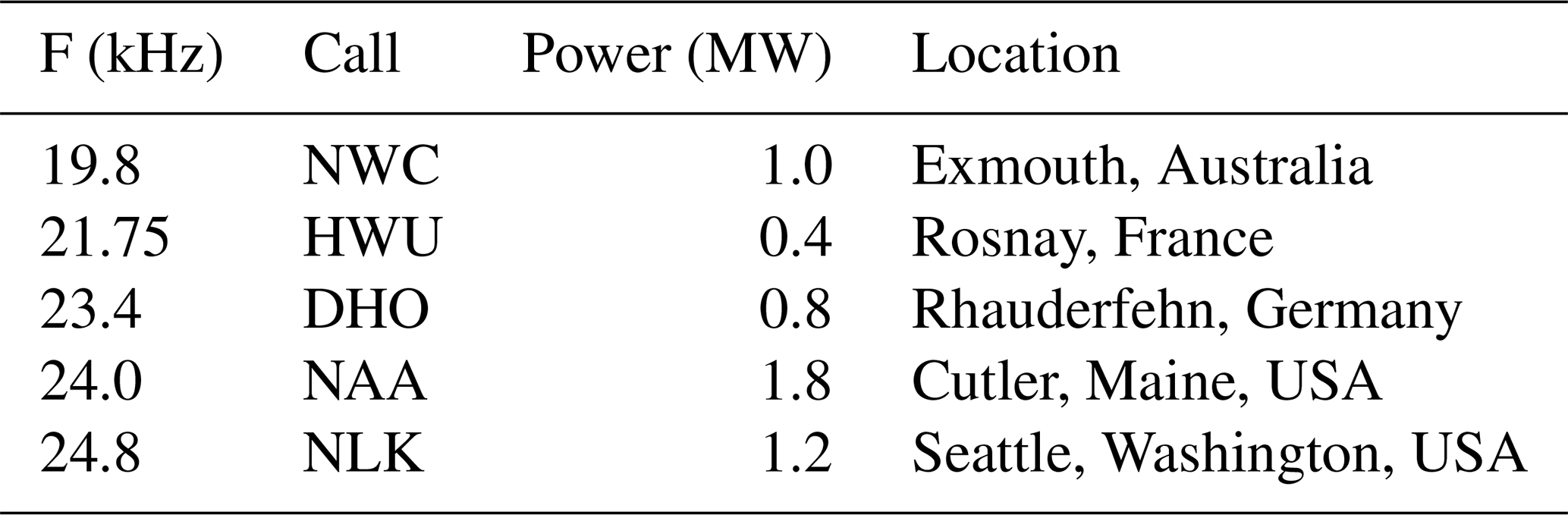
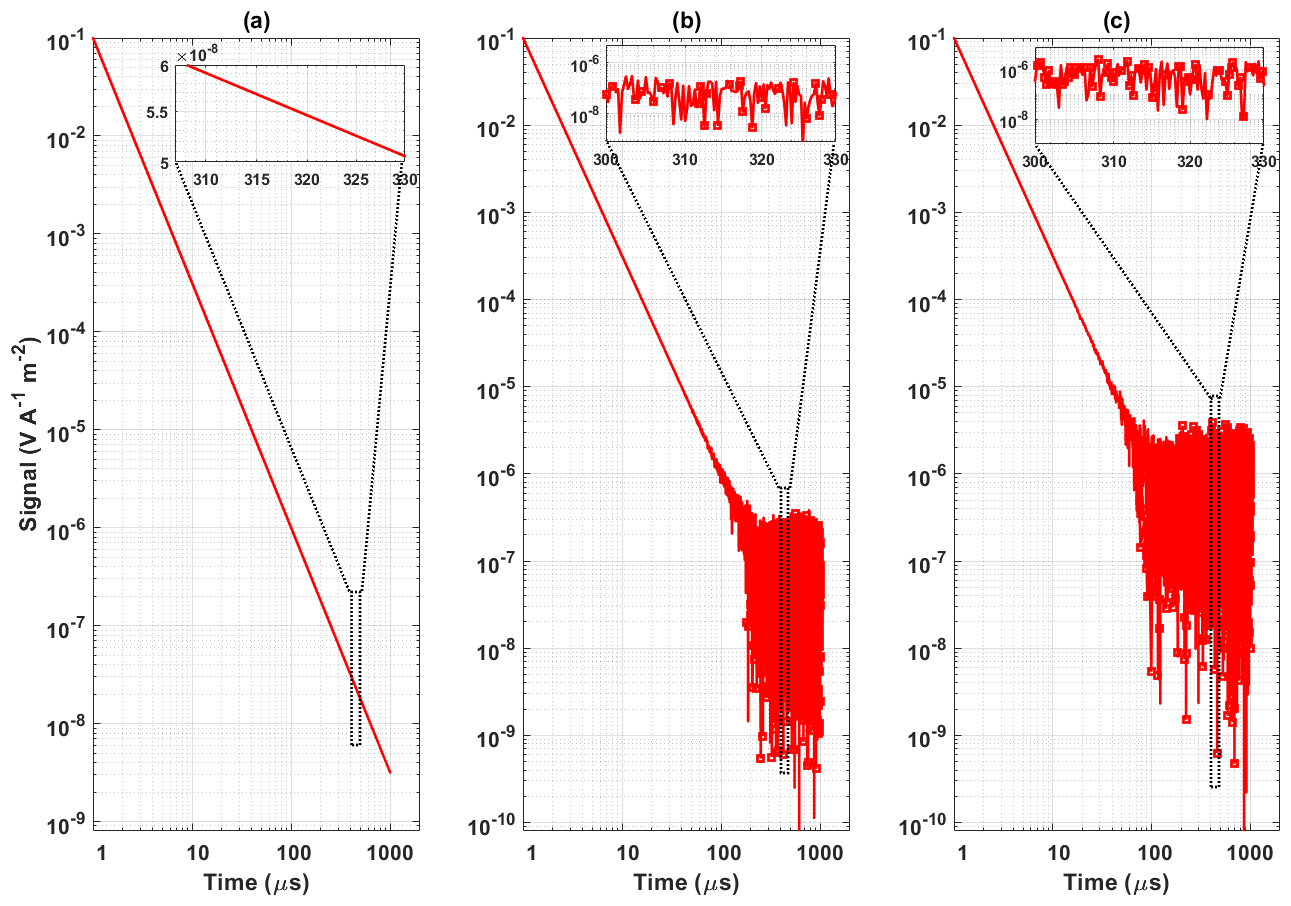
Figure 2Example of a decaying TEM signal. (a) Noiseless TEM, (b) TEM signal and random noise, and (c) TEM signal with random noise and VLF noise. The absolute values of negative samples of the noisy TEM signal are plotted and indicated with a square marker.
In practice, the power-line frequency is constant over a small duration. The correct choice of T0 ensures that the maxima and minima of the power-line noise are coherent with the TEM measurement. Therefore, synchronous detection, i.e., sign correction of the alternating sign pulses and subsequent stacking of the TEM signals, results in the cancellation of power-line noise and its harmonics. In countries with different power-line frequencies, normally 60 Hz, the repetition rate (T0) is changed to match the power-line frequency such that it results in cancellation after sign correction. The resultant TEM signal without noise and with noise is shown in Fig. 2. As negative values plotted on a log scale are ignored, these values are represented by a square marker by taking the absolute values. The magnified version of the TEM signal is shown in the upper box of Fig. 2b and c.
3.2 Gate bank
The current work selects standard gates based on their frequency, in particular side lobe properties. However, many other gate shapes can also be employed, but their properties are generally quite similar.
3.2.1 Boxcar gate
The rectangular or boxcar gate is an array of one defined for a desired interval in time. The mathematical formulation of a boxcar gate is defined as (Harris, 1978)
3.2.2 Hanning gate
The Hanning gate has a shape like one half-cycle of the cosine wave with a DC shift of 1, so it always remains positive. It is expressed as (Harris, 1978)
3.2.3 Hamming gate
The Hamming gate or window is a tapered gate formed by using a raised cosine like the Hann window, but with nonzero start and end points. It is also called the tapering or apodization function formulated as (Harris, 1978)
3.2.4 Kaiser gate
The Kaiser gate, also known as the Kaiser–Bessel window, approximates the prolate spheroidal window in which the ratio of the main lobe to the side lobe power spectral density is maximized. The attenuation in the side lobes is controlled by a tuning parameter β. Higher values of β increase the width of the main lobe and decrease the amplitude of the side lobes, thereby increasing the attenuation. The Kaiser window is defined as (Harris, 1978)
where I0 is the zeroth-order modified Bessel function of the first kind.
3.2.5 Gaussian gate
The Gaussian gate is called a bell curve gate and is the only function that Fourier-transforms itself with a smooth, nonzero function in the closed form. The mathematically Gaussian gate is denoted as (Harris, 1978)
3.2.6 Tukey's or fully tapered gate
Tukey's gate is a tapered cosine gate whose first and last edges follow a cosine shape, while the central follows the rectangular window. It is also called a fully tapered gate (Larsen et al., 2021). The mathematical expression defining Tukey's gate is (Harris, 1978)
where t1=mT and m represent the fraction of the window inside the cosine tapered region. The current work used a value of m=0.5, producing a Tukey window where of the entire window length consists of segments of a phase-shifted cosine with period 2m=1. A value of m=0 represents the rectangular or boxcar gate, and m>=1 is equivalent to the Hanning gate.
3.2.7 Semi-tapered gate
Here, a semi-tapered gate is defined as a piecewise flat approximation of the cosine part of the fully tapered or Tukey's window gate (Larsen et al., 2021).
3.2.8 B-Spline gate
The B-spline gate is formulated using the Cox-de-Boor recursive formula such that it is a composite curve of degree p polynomials, provides local support, and forms a partition of unity. The second-order B-spline function formulated is represented by (Nyboe and Mai, 2017)
where t0, t1, t2, and t3 are the time knots selected such that they are equally spaced in time. The resultant spline is a combination of three parabolas such that at any instant of time, the sum of weights for all parabolas active is unity. The gate shapes presented in the above subsection are in continuous time. In the current work, the piecewise flat gates have been constructed with a weighted combination of short analog boxcars called sub-gates.
3.3 Optimized and hybrid gating scheme
The suppression of VLF noise is accomplished by solving a multi-objective optimization problem such that a cost function composed of gate standard error bars, covariance between gates, and distortion of the gated TEM signal is minimized by varying the gate shape and gate width. Different gate shapes are inputted to the optimization problem to get the optimal solution. The multi-objective cost function used for obtaining the optimal gating scheme is defined as
where gopt is the optimum gate shape, Popt is the proportion of overlapping with the adjacent gate, E represents standard error bars, C represents the normalized covariance terms between gates, and D is the distortion of the noisy gated TEM signal. The gate locations are fixed because gate widths are designed so that they are exponentially widening. The current work considers a set of measurements composed of Nt transients, each containing Ng gated values. The data from the ith transient are stored in an Ng×1 vector:
The stacked (averaged) signal is computed as
Using this, the mean-removed data matrix is formed with size Ng×Nt as
from which the Ng×Ng covariance matrix is formed, which is denoted as
Due to the high dynamic range of TEM signals, which spans multiple orders of magnitude, careful normalization is required to ensure that all gates evenly contribute in the optimization.
The diagonal of the covariance matrix contains the variance of each gate. From this we form the Ng×1 vector E of signal-normalized standard errors with the elements . The off-diagonal terms are normalized by dividing the ijth element by , which therefore results in Pearson's linear correlation coefficient. The mean of C used in the optimization is computed from the absolute value of the normalized off-diagonal terms.
Finally, a signal-normalized measure of the distortion of the TEM signal is computed by forming the Ng×1 vector D as
where sideal is the ideal gated TEM signal without any noise modeled as a decay, snoise is the gated noisy TEM signal, and I is the identity matrix.
The MO-PSO is an evolutionary meta-heuristic optimization algorithm that has been used in various engineering and other applications (Coello Coello and Lechuga, 2002; Reyes-Sierra and Coello, 2006; Yang et al., 2022). The generic MO-PSO is to minimize
subject to the constraints
where w is a set of decision arrays, which is (g,P) in this work. Further, fk represents the objective functions, here (mean(E), mean(C), and mean(D)), k is the number of objective functions, and and are the constraint functions of the problem. The particle positions are iteratively updated with
where is the personal best of each particle in the search space obtained so far. The global best obtained so far is denoted by . The parameter that controls the search space of the particle's exploration is the inertia weight ψ, di is the scalar product of ai and ci where c1 and c2 are non-negative constants, while the values of a1 and a2 are within [0,1], and m is the current iteration. The variable corresponds to the update in position (from search space), i.e., update in the position and type of gate, whereas is the rate of velocity of the ith particle. The proposed work uses an MO-PSO algorithm to select the desired gate and its placement accurately. The variable wi,j(m) is the possible gate shape and its position, and the next position of the particle for the m+1 instance is obtained by adding its velocity vi,j(m) to wi,j(m). After each iteration, the personal best of each particle is obtained from a pool of search agents with the local best values for gate shape and position. Once the maximum number of specified iterations is completed, the global best solution is obtained, with the minimum values of objective functions. The randomness of the starting points in the MO-PSO search for the optimal solution implies that the algorithm can get trapped in a local minima. To overcome this limitation, the proposed work introduces confined search spaces where the first and second halves of the gates are each confined to only one shape. The current work denotes this confinement with two shapes as hybrid gating.
4.1 Synthetic model
The fully sampled synthetic TEM model is implemented in MATLAB (R2021a) on a 64-bit Windows operating system with an Intel(R) Core(TM) i7-8550U, 1.80 GHz CPU system with 16 GB of RAM. The current work generates the TEM, VLF, power-line interference, and RN at a 4 MHz sampling frequency. A total of 1000 TEM signals with a 1 ms duration are generated, decaying at a rate of ().
In the VLF model, a bandwidth of 100 Hz (Δf) for all radio signals is selected (Macnae, 2015). The model is designed such that for any user-defined number of VLFs, the system chooses random VLF radios to remove the bias between the choice and design of the VLF radio shown in Table 1. The signal record lengths are chosen so that stacking cancels power-line noise and its harmonics. The values of ARN and AVLF in Eq. (2) are selected such that distortions in resultant TEM signals start after 100 µs as observed in TEM data by Larsen et al. (2021). Three scenarios are used for the synthetic TEM data (TEM + RN + VLF radios), i.e., with one VLF radio, with four VLF radios, and with eight VLF radios for the analysis. The 4 MHz data stream is assembled into 84 boxcar gates to mimic the experimental conditions (Larsen et al., 2021). The boxcar gates are spaced approximately uniformly on a logarithmic timescale, except for the first 10 gates, which are distributed linearly in time, enforced by the 0.25 µs sampling period. Subsequently, the 84 gates are re-gated, i.e., linearly combined, into 30 gates with the re-gating being determined from the gate bank and optimization function. These 30 gates, denoted as production gates, are the final output, which can be used for inversion. The first gate of the final gate distribution is centered at 0.6 µs with 1 µs width, and the last gate is centered at 974.17 µs with 51 µs width. The first four gates of the final gates are distributed linearly and uniformly in time, while the rest of the gates are spaced uniformly on a logarithmic timescale. The first decade comprises eight gates, while the remaining decades contain 11 gates per decade. The weights of the final gates are normalized with respect to the raw gate width of analog boxcar gates to maintain the TEM signal value.
4.2 Field data
The field measurements have been recorded using a ground-based monitoring system based on analog boxcar gating (Zamora-Luria et al., 2022). The system consists of a transmitter coil (2 m × 4 m) and a receiver coil (0.5 m × 0.5 m) that are placed 7 m apart from the transmitter coil. Measurements of shallow and deep geological data have been accomplished using dual moments (low and high current transmitter pulses) corresponding to early- and late-time TEM recordings. Here, pulse repetition rates of 2110 and 630 Hz are used for low- and high-moment data recordings. Each low- and high-moment stack comprises 422 and 252 transients, respectively. A detailed system configuration can be found in Auken et al. (2019). Here, the focus is on the high-moment data with 84 gates spanning from 0.3 to 1130 µs, where the effect of VLF noise at late gate times can be significant.
The section presents the results obtained for the proposed model with synthetic and field data. In particular, the presence of VLF noise in the synthetic data is examined by the patterns produced in the CM, and the improvement by the optimized gating scheme is examined. Fully sampled data generated at the 4 MHz sampling frequency are assembled into 84 boxcar gates and used to form the CM in various noise scenarios (Fig. 3). When TEM signals are not affected by any VLF noise, gates are highly non-correlated, and the CM is nearly diagonal, as shown in Fig. 3a. When VLF noise is present in the data, the VLF noise decides the CM pattern. With multiple VLF radios operating at different amplitudes and frequencies, the resultant CM has dense stripes representing the higher correlation between the gates (Fig. 3b, c, and f). For fewer VLF radios, the patterns are less strong (Fig. 3d and e). Generally, with varying amplitude and combinations of VLF radios, the stripe pattern on the CM also varies. Therefore, this example demonstrates that correlation analysis using a CM can be used as a new tool to detect the presence of VLF interference in TEM data.
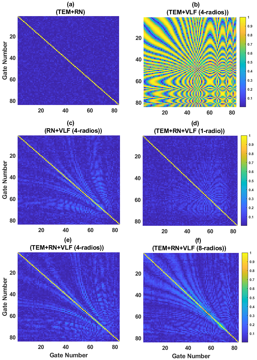
Figure 3The covariance matrices obtained for 84 boxcar gates. (a) TEM and random noise, (b) TEM + VLF noise, (c) random noise + VLF noise, (d) TEM with random and VLF noise (one VLF radio), (e) TEM with random and VLF noise (four VLF radios), and (f) TEM with random and VLF noise (eight VLF radios).
5.1 Synthetic data analysis
Fully sampled data generated at the 4 MHz sampling frequency are assembled into 84 boxcar gates. After obtaining the 84 boxcar gates, they are re-gated to 30 gates, where the MO-PSO is used to search for the best gate shape or combinations of gate shapes such that it minimizes the cost function. The optimization was tested for three different scenarios, i.e., TEM signals with random noise and either one, four, or eight VLF radios. A total of 1000 transients have been used for each scenario to find the optimal gate combination. Most frequently, a combination of boxcar and Hamming gates was obtained as the best solution, followed by semi-tapered boxcar and Hamming gates. Other gates have also been found as the best solution for the optimization problem; however, they occurred fewer times. From an entire solution space obtained at last, a hybrid combination of only boxcar and Hamming gates has been found to be the best solution for the majority of the transients.
The result of the final gate combination is such that for early times (gate numbers 1–10, from 0.3 to 30 µs) and mid-early times (gate numbers 11–15, from 30 to 80 µs), boxcar gates provide the best suppression in the VLF with low correlation and negligible standard error bars. During mid-late times, i.e., gate numbers 16–20 from 80 to 200 µs, and late times, i.e., gates 21–30 from 200 µs to 1 ms, the Hamming window gives a better performance.
Figure 4 shows a comparison of the CM obtained using boxcar gates, semi-tapered gates, and the hybrid gate scheme. The corresponding transients and error bars are shown in Fig. 5. It is evident from Fig. 4 that the boxcar gate suppresses VLF radios during early and mid-times, whereas the effect of the VLF is more significant at late times. When semi-tapered gating is used, it suppresses VLF radios at late times, but the early and mid-times are significantly affected by the presence of VLF noise. Analysis of standard error bars in the re-gated data shown in Fig. 5a reveals that the boxcar gates provide higher error bars for all three scenarios, i.e., TEM and RN with one, four, and eight VLF radios. This makes boxcar gates a poor choice during the late gates. The analysis of semi-tapered gates shows that the error bars produced by them are lower than those of boxcar gates and provide a smoother signal at late times. It has been observed that hybrid gating provides higher suppression of VLF radios than semi-tapered gates during early times.
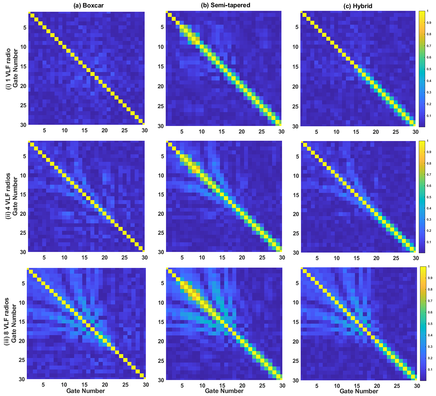
Figure 4Covariance matrices obtained after re-gating for TEM + RN + VLF noise with (i) one VLF radio, (ii) four VLF radios, and (iii) eight VLF radios with (a) boxcar gates, (b) semi-tapered gates, and (c) hybrid gates.
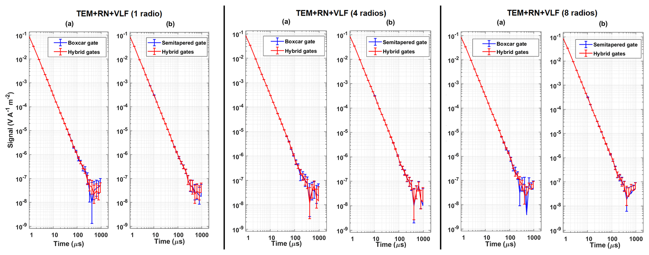
Figure 5Error bars obtained for the re-gated signal composed of TEM with random and VLF noise in the case of one, four, or eight VLF radios for (a) boxcar gates vs. hybrid gates and (b) semi-tapered gates vs. hybrid gates.
In contrast, during the mid-times and late times, the hybrid scheme suppresses the VLF radios better than boxcar gates. Similarly, the analysis of standard error bars reveals that the hybrid gating scheme provides small error bars in the early times, mid-times, and late times. The covariance and standard error bar analysis confirm that hybrid gating improves suppression of VLF radios. To further investigate the model's performance, this work also evaluates two improvement factors defined as (Larsen et al., 2021)
which measure the improvement in standard errors using either hybrid or semi-tapered gating relative to boxcar gating.
Table 2Improvement factors and associated standard deviation for gates 15 to 24 with synthetic data.
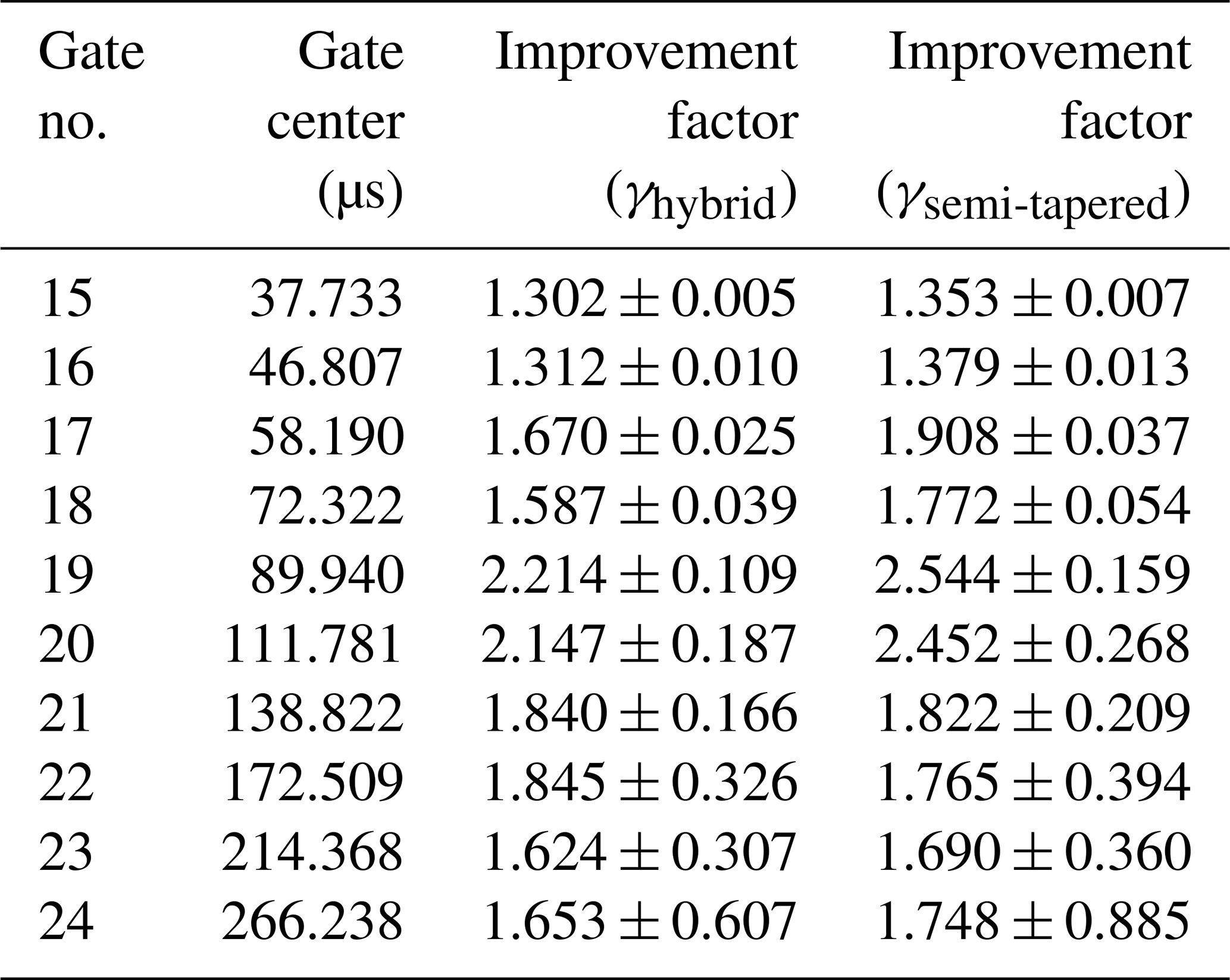
Table 3Mean value of covariance obtained for non-diagonal elements with different VLF radio combinations.
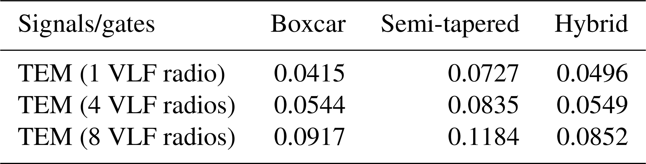
Table 4Mean distortion obtained for gate number 22 with different VLF radio combinations.
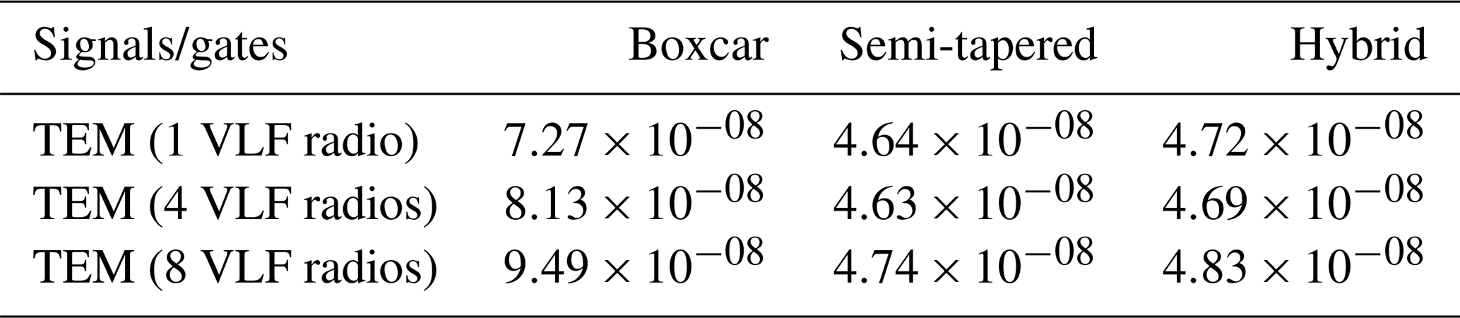
Table 2 shows the summary of the improvement factor obtained for gates 15–24 for 1000 TEM signals using semi-tapered and hybrid gates. It is evident from the table that the semi-tapered gates have a somewhat higher improvement factor compared to the hybrid gates, but the standard deviation is also higher. However, for gates number 21 and 22, the improvement factor provided by hybrid gates is higher than that of semi-tapered gates with smaller standard deviation. The effectiveness of the optimized model is further evaluated by obtaining the mean values of covariance and distortion for noisy TEM signals with different combinations of VLF radios. Tables 3 and 4 show the mean values of covariance and distortion obtained for different gates. It is evident from the tables that for the boxcar and semi-tapered gates there is a trade-off between covariance and distortion. Decreased covariance values with boxcar gates result in higher distortion, whereas lower distortion for semi-tapered gates results in increased covariance. However, hybrid gates provide an optimal solution with minimal correlation and distortion.
5.2 Field data analysis
The proposed hybrid gating model is also tested on the field data acquired from Kompedal Plantage, Denmark. A total of 313 signals have been used to analyze the effect of VLF noise on the gated data. The readings are measured using a buried monitoring TEM system. Each signal is a stacked combination of 252 transients of high-moment data containing 84 gates. All 252 transients are re-gated for each signal using the boxcar, semi-tapered, and the optimized hybrid gate model. After gating all the transients of each signal, they are stacked to form a 313×30 signal matrix.
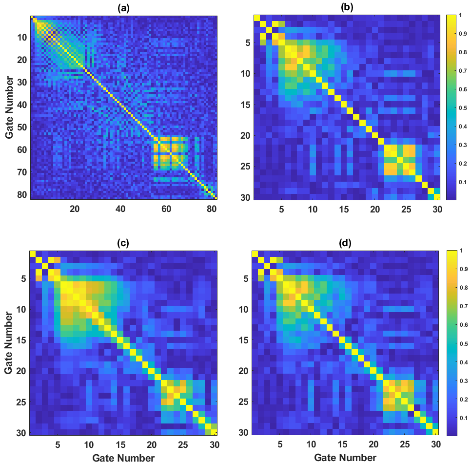
Figure 6Covariance matrices of field data before and after re-gating. (a) Raw gates, (b) boxcar re-gating, (c) semi-tapered re-gates, and (d) hybrid re-gating.
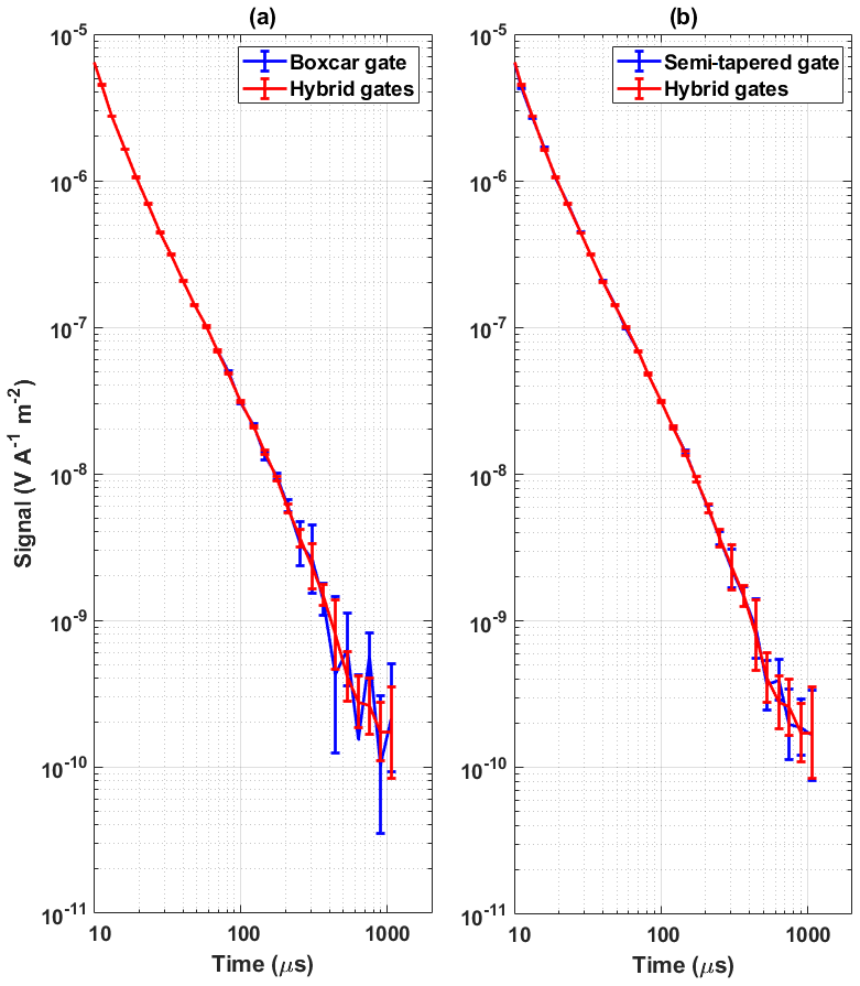
Figure 7Error bars obtained for the re-gated signal using field data for (a) boxcar gates vs. hybrid gates and (b) semi-tapered gates vs. hybrid gates.
Table 5Improvement factors and associated standard deviation for gates 15 to 24 with field data.
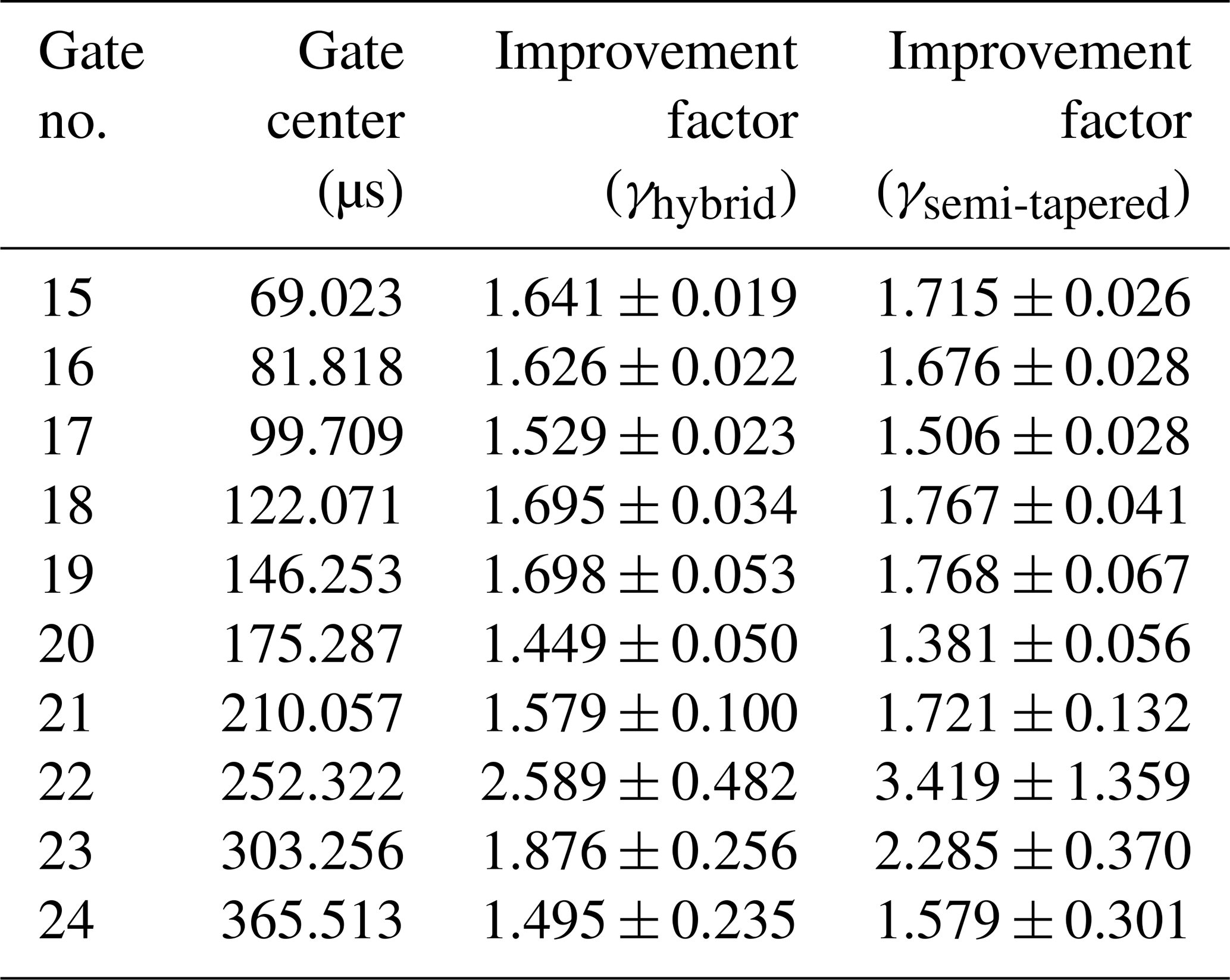
Figure 6a shows the CM obtained for the 84-gate signal, and the other panels show the re-gated (b) boxcar, (c) semi-tapered, and (d) hybrid gating results. Figure 7 illustrates the standard error bars obtained for the final gated signal using boxcar gates, semi-tapered gates, and the hybrid gating scheme. From Fig. 6a, it is seen that some stripes confirm the presence of VLF radios, whereas there are also some strong patterns in very early and late times, due to which a box-type structure is visible in the CM. The source of this structure is unidentified and may be due to some instrumental disturbances. It is evident from Figs. 6b and 7a that the boxcar gates result in a very strong pattern in CM in mid-times and late times and therefore provide higher error bars at late times. In contrast, the hybrid gating scheme suppresses off-diagonal terms in early and mid-times compared to the boxcar and semi-tapered gates and provides a very smooth decay of the TEM signal compared to a boxcar. Further, Fig. 7 shows that the hybrid gates provide lower values of standard error bars than boxcar gates.
Table 5 shows the summary of the improvement factor obtained with field data for gates 15–24 for 313 signals using semi-tapered and hybrid gates with respect to boxcar gates. Similar to the simulations, the higher improvement factor provided by the semi-tapered gates comes with a higher standard deviation. Also, a higher improvement factor in the time-domain analysis does not guarantee suppression of VLF in the frequency domain, as seen in the case of the semi-tapered gate. The mean values of covariance are obtained as 0.1538, 0.1894, and 0.1711 for boxcar, semi-tapered, and hybrid gates, respectively. Due to practical constraints, i.e., the impossibility of obtaining the ideal decay from the instruments for the field data, it is not possible to measure distortion in field data. The analysis reveals that the existing semi-tapered gates that reduce standard error bars with better improvement factors have a high correlation between the gates, which is reflected in the CM. On the other hand, the hybrid gate combination has not only provided an improvement over boxcar gates in the time-domain analysis by minimizing the standard error bars, but also significantly suppressed the VLF in the mid-times and late times. Thus, the hybrid scheme is a better choice for gating the TEM data because it not only provides smaller error bars and reduced correlation between the gates than boxcar gates at late times, but also reduces the correlation of gates in early and mid-times compared to the semi-tapered gates.
5.3 Frequency response analysis
Figure 8a illustrates the time-domain gate shapes, while panel (b) shows the corresponding frequency-domain response for boxcar, semi-tapered, and piecewise flat Hamming gates. Notably, each tapered and squared part of the semi-tapered gate comprises four sub-gates, while for the Hamming gate it comprises five sub-gates. The gates are designed to appear symmetric on a logarithmic time axis and will therefore appear asymmetric on a linear time axis. The frequency response is normalized to a unit gain at 0 Hz. It is clear from Fig. 8 that the frequency response provided by boxcar gates has significant side lobes, which can pass the VLF radios. The frequency response offered by the semi-tapered gate provides better suppression of the VLF radios due to smaller amplitudes of the side lobes. The arrows represent the location of common VLF radios in the frequency spectrum. It is seen from the frequency response of semi-tapered, Hamming, and boxcar gates that the side lobes can pass the VLF radios. The frequency response of the semi-tapered and Hamming gates offers a very low amplitude of early and mid-side lobes, resulting in stronger suppression of VLF radios.
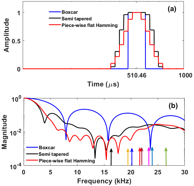
Figure 8Comparative analysis of boxcar, semi-tapered, and piecewise flat Hamming gates (gate number 27) centered at 510.46 µs. The width of the boxcar gate is 126.75 µs, whereas the width of the semi-tapered and piecewise flat Hamming gate is 388.06 µs. (a) Time-domain analysis and (b) frequency-domain analysis. The colored arrows in (b) show the frequencies of VLF radios.
The total decay time of one TEM signal can roughly be divided into three regions: early times between gates 1 and 10 spanning from 0.3 to 30 µs, mid-times between gates 11 and 20 spanning 30 to 200 µs, and late times between gates 21 and 30 spanning 200 to 1130 µs. At early times, VLF frequencies appear inside the main lobe due to smaller gate widths (a few µs). However, the amplitude of the TEM signal dominates over VLF radio noise having a very high SNR; therefore, the effect of the VLF is not dominant, resulting in smooth and undistorted decays of TEM signals. At mid-times, the edges of the main lobe and the first side lobes align with the frequency of VLF radios. Due to this, VLF radio signals can be present in gated data. However, if the amplitude of TEM signals is higher than that of the VLF radios, the TEM signal decays smoothly. On the other hand, if the amplitudes of VLF radios are dominant over signal amplitude, there might be distortion in the resultant gated data. Finally, in the late times, the side lobes of boxcar gates align within the frequency of the VLF radios, thus producing strong off-diagonal terms in the covariance plots. Here, the hybrid gates provide better suppression of VLF radios due to lower-amplitude side lobes compared to semi-tapered and box-car gates. Thus, it is clear from the analysis that the Hamming or the semi-tapered gating scheme is very effective at the late times for the suppression of VLF radios with less distortion in the TEM signal. This makes it clear that the proposed scheme shows overall improvement in terms of time-domain and frequency-domain analysis. Also, gating does not entirely suppress the effect of VLF radios in the resultant gated signals.
The proposed hybrid gating model is configured according to the current towed-TEM system. In the future, data from a fully sampled system will be used for the analysis. The data will be gated using fully sampled gates as shown in Fig. 9. For a fair comparison with the existing gating scheme, the proposed work also compares the frequency response of an existing fully sampled B-spline gate (Nyboe and Mai, 2017; Peng et al., 2022). The frequency response observed for the fully sampled Hamming gate has improved suppression of VLF radios beyond 20 kHz over the piecewise flat Hamming gate. Frequency analysis also reveals that the fully sampled Hamming gate has a better suppression of VLF over existing B-spline gates. It has been observed that Hamming gates have sharp zeros and low magnitudes compared to B-spline gates, offering better possibilities of suppressing some VLF radios completely. Thus, it is clear from the analysis that fully sampled gating with Hamming gates will have better suppression of VLF over boxcar, semi-tapered, and piecewise flat Hamming gates.
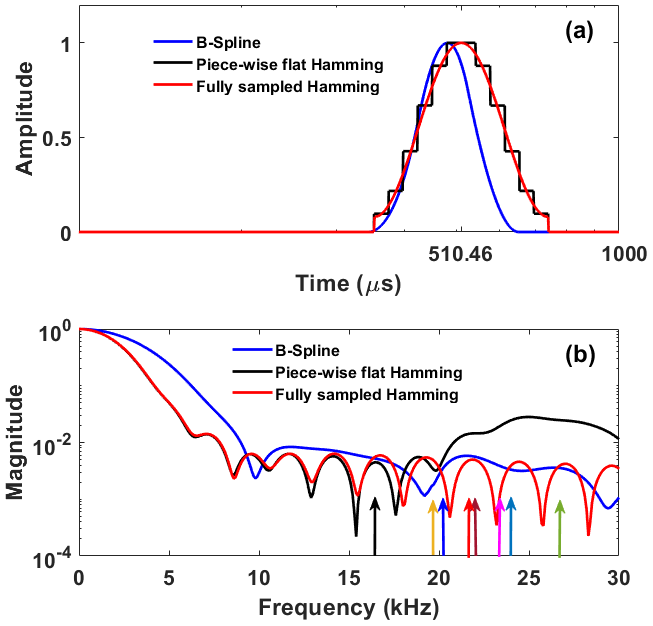
Figure 9Comparative analysis of a B-spline (gate number 27) gate centered at 472.94 µs, a piecewise flat Hamming gate, and fully sampled Hamming gates (gate number 27) centered at 510.46 µs. The width of the B-spline gate is 308.78 µs, and the width of the Hamming gate is 388.06 µs. (a) Time-domain analysis and (b) frequency-domain analysis. The colored arrows in (b) show the frequencies of VLF radios.
5.4 Discussion
This section compares the analysis of the current work with existing literature. Larsen et al. (2021) explored the usage of semi-tapered gates to suppress VLF radios. The method used a linear combination of boxcar gates to construct a flat-top tapered gate. The semi-tapered gates are selected such that they minimize the standard errors with respect to short boxcar gates. The semi-tapered gating scheme has obtained an average improvement factor of 1.514. However, optimization of a gate with a single standard error objective may pass some of the VLF radios due to its coherent nature. The analysis only focused on field data, whereas the analysis of synthetic data with different numbers of VLF radios was missing. Also, their analysis lacked covariance between the gates.
Traditionally, the system response for SkyTEM is evaluated using model-based interpolation (Nyboe and Mai, 2017). Nyboe and Mai used B-spline gating to reduce the data size captured from a fully sampled airborne system (Nyboe and Mai, 2017). The method showed that the high sampling rate and B-spline gating function eliminate the need for a model-based interpolation. However, a detailed discussion about the amount of data and noise reduction achieved using B-spline gating was not given in this paper, nor were qualitative and quantitative model performances for different scenarios using time- and frequency-domain analysis presented.
Peng et al. (2022) demonstrated the usage of B-spline gating for TEM data. The analysis shows that the suppression of VLF radio at a frequency of 24.1 kHz is better for B-spline gates than short boxcar, long boxcar, and fully tapered gates. An improvement in standard errors of about 15 % has been achieved compared to fully tapered gates. However, their analysis does not consider multiple VLF radios active at a single instance of time. Thus, optimizing the frequency response of one B-spline gate for a particular VLF radio can pass other VLF radios unaltered. Similarly, their analysis did not consider the covariance between the gates, which is common due to the overlapping frequency response of the adjacent gates.
The proposed model overcomes these issues mentioned in the above literature. The proposed model considered three constraints for optimization, namely minimization of standard errors, covariance, and distortion. The proposed model extends the analysis to synthetic and field data with varying VLF contents. Analysis shows that the proposed model has obtained collective improvement in standard errors with a minimum standard deviation and suppression in covariance of adjacent gates. The average improvement factor obtained for the hybrid gating scheme is 1.719 and 1.717 with synthetic and field data, respectively. The analysis also reveals that simulations based on fully sampled gates offer higher suppression in VLF radios than the existing semi-tapered and B-spline gates. Thus, the proposed model has collectively surpassed the performance of the existing gating scheme for an entire recording duration. The total time required for selecting an optimized gate for one signal was about 17 min. Also, the time required to select the optimum gate increased with an increase in the number of iterations and search agents. It is impractical to use multi-objective particle swarm optimization on a daily basis on, e.g., remote monitoring systems with limited computing resources. Here, an alternative solution is to use the optimization results to generate a set of a few representative and nearly optimum gate banks. Deciding which of these gate banks is optimum for any given measurement is a low-computing-cost operation.
The means of constraints, i.e., the minimum standard error, minimum correlation between off-diagonal terms, and minimum distortion, are used to obtain the optimal combination of gates. The optimal gate is then used to obtain the final gated signal for synthetic and field data. However, in real scenarios, it is not possible to measure the decay of a signal without noise. Therefore, repetition of simulations with only two constraints (minimum standard error, minimum correlation between off-diagonal terms) has also been considered. It has been observed that with two constraints the choice of gate selection varies more frequently from one gate to another (mainly between hybrid and semi-tapered gates). In addition, the optimum hybrid gate design is obtained for a noise model that provides VLF noise of the same amplitude without considering the fluctuations that occurs in real measurements, i.e., daily changes in environmental and atmospheric conditions leading to a varying strength of VLF radio signals. Such variations may affect the optimal gate placement or their types. A different combination of gate shapes may therefore be obtained due to variations in the environmental conditions in field data.
The CM obtained after gating the field data indicates the presence of a strong pattern at the late times. Thus, the field data appear to be contaminated by another noise source. A detailed study of daily changes could potentially help identify the noise source(s) and be used in the development of a more robust or adaptive algorithm with improved noise suppression. This, however, is delegated to future investigations.
The proposed hybrid gating scheme is a new technique designed for fully sampled and existing TEM systems with analog boxcar gates. The hybrid gating scheme is a combination of boxcar and Hamming gates. The developed gating technique has provided minimal distortion in the final gated signal, and it also minimizes covariance at mid-times and late times as well as standard errors for early and late gates. The developed technique is a promising tool to suppress VLF radio noise during the mid-times and late times. The covariance analysis provides an analysis of VLF noise and other coherent sources. The developed technique is not only applicable to the existing analog boxcar integrator TEM systems, but will also be ready to be deployed on fully sampled digital systems. In the future, analysis of more noise sources and solutions to suppress these sources will be examined.
Data used in this work are available upon request to the corresponding author
SKK: data collection, conceptualization, methodology, writing (original draft), and validation. PM: data collection, validation, reviewing, and editing. PKM: data collection and reviewing. JJL: conceptualization, validation, reviewing, and editing.
The contact author has declared that none of the authors has any competing interests.
Publisher's note: Copernicus Publications remains neutral with regard to jurisdictional claims made in the text, published maps, institutional affiliations, or any other geographical representation in this paper. While Copernicus Publications makes every effort to include appropriate place names, the final responsibility lies with the authors.
This research has been supported by Innovation Fund Denmark (grant no. 0177-00085A).
This paper was edited by Lev Eppelbaum and reviewed by two anonymous referees.
Auken, E., Boesen, T., and Christiansen, A. V.: Chapter Two – A Review of Airborne Electromagnetic Methods With Focus on Geotechnical and Hydrological Applications From 2007 to 2017, Adv. Geophys., 58, 47–93, https://doi.org/10.1016/bs.agph.2017.10.002, 2017. a
Auken, E., Foged, N., Larsen, J. J., Lassen, K. V. T., Maurya, P. K., Dath, S. M., and Eiskjær, T. T.: tTEM – A towed transient electromagnetic system for detailed 3D imaging of the top 70 m of the subsurface, Geophysics, 84, E13–E22, https://doi.org/10.1190/geo2018-0355.1, 2019. a, b, c
Chen, J., Jia, W., Zhang, Y., and Lin, J.: Integrated TEM and GPR Data Interpretation for High-Resolution Measurement of Urban Underground Space, IEEE T. Instrum. Meas., 71, 1–9, https://doi.org/10.1109/TIM.2021.3134995, 2022. a, b
Chen, S., Zhang, S., Zhu, J., and Luan, X.: Accurate Measurement of Characteristic Response for Unexploded Ordnance With Transient Electromagnetic System, IEEE T. Instrum. Meas., 69, 1728–1736, https://doi.org/10.1109/TIM.2019.2917236, 2020. a
Christiansen, A. V., Auken, E., and Sørensen, K.: The transient electromagnetic method, 179–226, Springer, https://doi.org/10.1007/978-3-540-88405-7_6, 2009. a
Coello Coello, C. and Lechuga, M.: MOPSOs: a proposal for multiple objective particle swarm optimization, in: Proceedings of the 2002 Congress on Evolutionary Computation. CEC'02 (Cat. No.02TH8600), vol. 2, 1051–1056, https://doi.org/10.1109/CEC.2002.1004388, 2002. a
Cohen, M.: The Stanford University ELF/VLF receiver–Narrowband transmitter guide, http://solar-center.stanford.edu/SID/AWESOME/docs/AWESOME%20Transmitters.pdf (last access: 3 November 2023), 2006. a, b
Eppelbaum, L. and Mishne, A.: Unmanned Airborne Magnetic and VLF Investigations: Effective Geophysical Methodology for the Near Future, Positioning, 2, 112–133, https://doi.org/10.4236/pos.2011.23012, 2011. a
Harris, F.: On the use of windows for harmonic analysis with the discrete Fourier transform, P. IEEE, 66, 51–83, https://doi.org/10.1109/PROC.1978.10837, 1978. a, b, c, d, e, f, g
Inan, U. S., Cummer, S. A., and Marshall, R. A.: A survey of ELF and VLF research on lightning-ionosphere interactions and causative discharges, J. Geophys. Res.-Space, 115, A00E36, https://doi.org/10.1029/2009JA014775, 2010. a
Kavanagh, A. J., Denton, M., Denton, J., and Harron, H.: Probing geospace with VLF radio signals, Astron. Geophys., 52, 2–27, https://doi.org/10.1111/j.1468-4004.2011.52227.x, 2011. a
Kuo, H.-H.: White noise distribution theory, CRC press, https://doi.org/10.1201/9780203733813, 2018. a
Larsen, J. J., Pedersen, S. S., Foged, N., and Auken, E.: Suppression of very low frequency radio noise in transient electromagnetic data with semi-tapered gates, Geosci. Instrum. Meth., 10, 81–90, https://doi.org/10.5194/gi-10-81-2021, 2021. a, b, c, d, e, f, g, h, i
Law, D., Noh, K. A. M., and Rafek, A. G. M.: Application of Transient Electromagnetic (TEM) Method for Delineation of Mineralized Fracture Zones, IOP C. Ser. Earth Env., 279, 012038, https://doi.org/10.1088/1755-1315/279/1/012038, 2019. a
Liu, F., Lin, J., Wang, Y., Wang, S., Cao, X., and Chen, B.: Design of Cable Parallel Air-Core Coil Sensor to Reduce Motion-Induced Noise in Helicopter Transient Electromagnetic System, IEEE T. Instrum. Meas., 68, 525–532, https://doi.org/10.1109/TIM.2018.2849520, 2019. a, b
Macnae, J.: Stripping very low frequency communication signals with minimum shift keying encoding from streamed time-domain electromagnetic data, Geophysics, 80, E343–E353, https://doi.org/10.1190/geo2015-0304.1, 2015. a, b, c
Macnae, J. C., Lamontagne, Y., and West, G. F.: Noise processing techniques for time‐domain EM systems, Geophysics, 49, 934–948, https://doi.org/10.1190/1.1441739, 1984. a, b
Mulè, S., Miller, R., Carey, H., and Lockwood, R.: Review of three airborne EM systems, ASEG Extended Abstracts, 2012, 1–5, https://doi.org/10.1071/ASEG2012ab352, 2012. a
Nabighian, M. N. and Macnae, J. C.: 6. Time Domain Electromagnetic Prospecting Methods, in: Electromagnetic Methods in Applied Geophysics: Volume 2, Application, Parts A and B, chap. 6, 427–520, SEG Library, https://doi.org/10.1190/1.9781560802686.ch6, 1991. a, b, c
Nyboe, N. and Mai, S.: Recent Advances in SkyTEM Receiver System Technologies, in: Second European Airborne Electromagnetics Conference, European Association of Geoscientists & Engineers, 1–5, https://doi.org/10.3997/2214-4609.201702157, 2017. a, b, c, d, e
Oskooi, B. and Pedersen, L.: Comparison between VLF and RMT methods: A combined tool for mapping conductivity changes in the sedimentary cover, J. Appl. Geophys., 57, 227–241, https://doi.org/10.1016/j.jappgeo.2005.01.002, 2005. a
Pedersen, L. and Oskooi, B.: Airborne VLF Measurements and Variations of Ground Conductivity: A Tutorial, Surv. Geophys., 25, 151–181, https://doi.org/10.1023/B:GEOP.0000028161.90659.4b, 2004. a
Peng, C., Zhu, K., Fan, T., and Yang, Y.: Suppressing the very low-frequency noise by B-spline gating of transient electromagnetic data, J. Geophys. Eng., 19, 761–774, https://doi.org/10.1093/jge/gxac049, 2022. a, b, c, d, e
Rasmussen, S., Nyboe, N. S., Mai, S., and Larsen, J. J.: Extraction and use of noise models from transient electromagnetic data, Geophysics, 83, E37–E46, https://doi.org/10.1190/geo2017-0299.1, 2018a. a
Rasmussen, S., Nyboe, N. S., Mai, S., and Larsen, J. J.: Robust cancellation of minimum shift keying-encoded radio interference in data from the transient electromagnetic method, Geophysics, 83, E87–E94, https://doi.org/10.1190/geo2017-0611.1, 2018b. a, b, c
Reyes-Sierra, M. and Coello, C.: Multi-Objective Particle Swarm Optimizers: A Survey of the State-of-the-Art, International Journal of Computational Intelligence Research, 2, 287–308, https://doi.org/10.5019/j.ijcir.2006.68, 2006. a
Yang, Y., Liao, Q., Wang, J., and Wang, Y.: Application of Multi-Objective Particle Swarm Optimization Based on Short-Term Memory and K-Means Clustering in Multi-Modal Multi-Objective Optimization, Eng. Appl. Artif. Intell., 112, 104866, https://doi.org/10.1016/j.engappai.2022.104866, 2022. a
Zamora-Luria, J., McLachlan, P., Grombacher, D., Maurya, P., and Christiansen, A.: Monitoring Water Table Variations In An Unconfined Aquifer Using a Time-Lapse TEM Method, NSG2022 28th European Meeting of Environmental and Engineering Geophysics, 1–5, September 18-22, 2022, Belgrade, Serbia, https://doi.org/10.3997/2214-4609.202220032, 2022. a, b
Zhang, K. Q.: Wireless Communications: Principle, theory and methodology, John Wiley & Sons, Ltd, https://doi.org/10.1002/9781119113263, 2015. a