the Creative Commons Attribution 3.0 License.
the Creative Commons Attribution 3.0 License.
Geological stratigraphy and spatial distribution of microfractures over the Costa Rica convergent margin, Central America – a wavelet-fractal analysis
Upendra K. Singh
Rahul Prajapati
Thinesh Kumar
Identification of spatial distribution of lithology as a function of position and scale is a very critical job for lithology modelling in industry. Wavelet transform (WT) is an efficacious and powerful mathematical tool for time (position) and frequency (scale) localization. It has numerous advantages over Fourier transform (FT) to obtain frequency and time information of a signal. Initially continuous wavelet transform (CWT) was applied on gamma ray logs for identification of lithofacies distribution, and later discrete wavelet transform (DWT) was applied on density logs to identify the fracture zones. In this study the data were taken from two different well sites (well 1039 and well 1043) of the Costa Rica convergent margin, Central America. The CWT analysis provides four major sedimentary layers terminated with a concordant igneous intrusion passing through both the wells. In addition, the wavelet-based fractal analysis (WBFA) technique was applied on identified sedimentary successions, and fractal-dimension (FD) values were calculated for every succession to know the presence and distribution of fractures. We found that the second and third successions have a high FD value, whereas the first and fourth successions have a low FD value. These high values may be due to the presence of abundant shale content and low-energy environments in the sedimentary successions.
- Article
(3211 KB) - Full-text XML
- BibTeX
- EndNote
Manual interpretations of well log signals, which have very noisy and highly fluctuations in nature, are quite difficult and require more experience and sophisticated techniques/software. These difficulties are minimized by a kind of wavelet transform (WT) method. In our study continuous wavelet transform (CWT) is tested on generated synthetic signals and applied to field data. The analysed results prove that the CWT is highly suitable in geophysical log signals, whereas the conventional fast Fourier transform (FFT) fails in this case because it considers the whole signal in a stationary form. Though WT provides unambiguous results in analysing the noisy and non-stationary signals, its efficiency in extracting the information from the signal was seen through its wavelet coefficients (Liu and Jian, 2010) with wavelet scalogram.
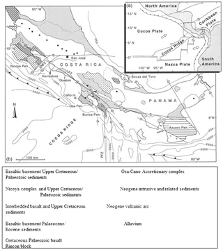
Figure 1Geological and tectonic map of the Costa Rica convergent margin, Central America (modified after Case and Holcambe, 1980).
A number of publication have come to identify the lithofacies boundary using mother wavelet transform and Fourier transform, amongst other techniques (Chandrasekhar and Rao, 2012; Coconi et al., 2010; Dashtian et al., 2011; Javid and Tokhmechi, 2012; Mansinha et al., 1997; Pinnegar and Mansinha, 2003, 2004; Li et al., 2004, Pan et al., 2008; Zhang et al., 2011; Singh, 2011; Singh et al., 2010; Stockwell et al., 1996,2007; Sahimi and Hashemi, 2001; Tokhmechi et al., 2009a, b; Yue et al., 2004; Zhang et al., 2011). Some other authors have worked on WT to describe the scaling property using magnetic susceptibility data (Fedi, 2003), and Bansal et al., (2010) have determined the presence of fractures using power law scaling behaviour of magnetic susceptibility and density variation in continental crust.
In this paper, CWT and discrete wavelet transform (DWT) are used separately for identifying the lithology using gamma ray log data of well sites 1039 and 1043 obtained from the Costa Rica convergent margin, Central America (Expedition 308 scientists, 2005), as shown in the geological and tectonic map of Fig. 1. The detailed geology and tectonic setting of the study area were discussed clearly by Case and Holcambe (1980). Moreover, the fracture zones present in some of the sedimentary succession of both wells are analysed by DWT. The DWT-analysed results give a significant linear relationship between the fracture density and identified fractures from water saturation logs, even though logging datasets do not reflect clear signals of fracture zones. Additionally, the wavelet-based fractal analysis (WBFA) technique was applied, and fractal dimension (FD) was calculated to characterize the roughness of the fractures in some of the identified sedimentary layers of both well sites 1039 and 1043. The obtained results suggest that the second and third successions have a high FD value, whereas the first and fourth successions have a low FD value. These high values may be due to the presence of abundant shale content and low-energy environments in the sedimentary successions. Thus the proposed DWT technique acts as a microscope to clearly identify and distinguish the high and low frequency of hidden log signals, and fractal dimension is highly useful for characterizing the fracture density and spatial distribution of fracture zones.
2.1 Wavelet transform
Wavelet transform is a mathematical tool that can be used to analyse both stationary and non-stationary signals (Daubechies, 1990, 1992) and expand time series into time frequency space. Therefore, this method can find localized intermittent periodicities. For analysing stationary or non-stationary signal, a proper mother wavelet has to be substituted and the operation of continuous wavelet transform (CWT) proceeds as the convolution between time series of our interest. The Discrete wavelet transform (DWT) is very useful in the case of noisy data. It compresses the data by reducing noise and improves the resolution, whereas the application of CWT prefers to extract the lithological feature from data. As it exposes the signal to high- and low-frequency filters to form approximate and detailed coefficients, it traces out the abrupt changes in the signal. Basically, in geophysical well logs the abrupt change corresponds to its own individual parameter changes, which provide us more information about the subsurface stratigraphy. This methodology pertaining to DWT allows us to locate the high-frequency changes immersed in the log which cannot be identified manually. For example, a gamma ray log is a good lithology indicator, but in certain conditions it fluctuates highly in nature. This nature sometimes perturbs its evaluation. Apart from lithology identification, DWT provides an advantage in analysing the fracture identification. Choice of mother wavelet is an important factor for analysing the non-stationary signal. Here we have applied and tested a kind of mother wavelet on well log signals to select the optimum wavelet tools, in which the Coiflet 4 wavelet provides better results.
In this method, our analysis is based on linearity between the logarithm of wavelet coefficients (logσ) and scale. Regression coefficients R2 for all log signals from each well have been calculated, and a linear fit was obtained for the Coiflet 4 wavelet. The wavelets do not give a significant change in wavelet coefficients to identify stratigraphy boundary. Thus the Coiflet 4 wavelet is best for analysis of this well log data.
2.1.1 Continuous wavelet transform
The concept of continuous wavelet transform can be explained by a basic equation given below:
where f(x) is the time series of our interest; φ(x) is the mother wavelet; a is the scaling parameter, which is the inverse of frequency; b is the translation parameter directly proportional to time; and n is the normalizing parameter, which is equal to 1 (say). The scaling parameter “a” is defined in terms of frequency as
and the variance of wavelet coefficients follows a power law relation with the scale is defined as
Here F is the frequency and Fc is the centre frequency of the wavelets, Δ is the sampling interval, v is the variance of wavelet coefficients, x is the scale, and h is the holder/wavelet exponent.
The holder/wavelet exponent provides the measure of roughness/smoothness. If the holder exponent values are high, it accounts for smoothness, whereas low holder exponent values emphasize more roughness. After obtaining the holder exponent, it can be substituted in the equation given below to obtain the fractal-dimension value:
where D is the FD that is computed using the holder exponent and the variance of wavelet coefficient known as WBFA.
2.1.2 Discrete wavelet transform
A one-dimensional discrete wavelet transform has been carried out in this task as per the datasets, which are discrete and one-dimensional. For the construction of DWT, one sets a=2j and b=2jk, where j and k are both integers. One-dimensional DWT is given by the following equation:
where f(t) is the time series of our interest and , where n is the discrete data array of maximum size. Time series data of our interest are decomposed to approximate and detailed coefficients, providing both lower- and higher-frequency information.
3.1 Application to synthetic data
A synthetic signal is generated using a sinusoid function (sin2πft) with three different frequencies: 3, 5, and 10 Hz. The CWT is applied on a generated synthetic signal without noise and also on signals with 25 % Gaussian white noise. The result obtained using signal without noise and with noise are shown in Fig. 2a and b, respectively. As the signal is free from noise, thus possessing only its own frequencies, the mathematical tools did not pose any difficulty, and the information required is derived without any ambiguity. When the same signal is analysed by the above-mentioned techniques after mixing noise, it provides large differences in the results, which are shown in Fig. 2b. The CWT provides an acceptable picture in analysing the non-stationary as well as the same non-stationary signal mixed with noise. CWT removes the ambiguity not only by forming wavelet modulus maxima but also through its wavelet coefficients. Also it provides a picture of the time–frequency localization in interpretable form. An advantage pertaining to wavelet transform is that the wavelet coefficients record more reliable information of the signal even if it is noisy. Thus CWT proves to be a good tool for identification of lithology in well logs, and it can be useful in all circumstances to derive information in the signal.
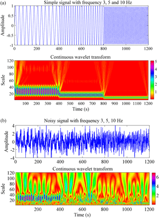
Figure 2(a) The continuous wavelet transform (CWT) using synthetic time series data and (b) the CWT of synthetic noisy time series data.
Generally, porosity logs are used for this approach, and the fluctuating nature of the porosity logs can be correlated with both pores distribution and the fracture (major as well as several microfractures) as well. DWT differentiates both fractures and the characteristics of the pores in the detailed coefficients (Sahimi and Hashemi, 2001). For demonstration of the techniques, we have generated two types of synthetic well logs: (i) assuming a well site is fractureless and (ii) assuming a well site is fractured. Now wavelet detail coefficients (WDCs) for both well site are calculated as shown in Fig. 3. The highly differentiable features/signals are observed in Fig. 3d. We observed from WDC analysis that will be containing highly differentiable features in terms of spikes or local maxima as shown in Fig. 3d. The noisy data points pertaining to the uniform distribution constitute both low and high values in comparison with surrounding data points. DWT differentiates these particular locations by means of a spike irrespective of the magnitude of the data points which are replaced. As DWT works as low- and high-frequency filters, detailed and approximate coefficients are produced.
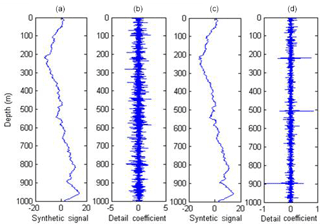
Figure 3(a) Synthetic well log data over the fractureless well site, (b) discrete wavelet detail coefficient (DWC) of the fractureless well site, (c) synthetic well log data over the fractured well site, and (d) DWC of the fractured well site.
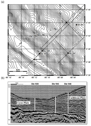
Figure 4(a) Bathymetry map with an interval of 20 m (b), seismic depth section along with the well site of the study area (after Moritz et al., 2000).
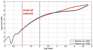
Figure 5Scale of interest showing variance of wavelet coefficients versus scale of gamma ray of well sites 1039 and 1043.
3.2 Application of field data: Costa Rica convergent margin, Central America
The Costa Rica convergent margin in Central America is a subduction zone due to the convergence of the Cocos and Caribbean plates. Figure 4a shows the bathymetry map, and Fig. 4b shows the location of well sites and the seismic depth section of the study area. The seismic-migration section over the region shows well sites 1039, 1040, and 1043 (Fig. 4b). In our study, gamma ray and density log data are taken for analysis from the well sites 1039 and 1043, whereas the site 1040 is omitted because it does not pass through certain major litho-units. Conventional techniques such as fast Fourier transform fail to provide the time–frequency localization (Pan et al., 2008). In order to solve these problems, the wavelet transform is applied to find out the proper time–frequency localization. Our study is confined to mainly three parts: (i) lithological/lithofacies identification using gamma ray logs by CWT because the gamma ray signals exhibit sharp spikes which are predictable due to the presence of interbedded ash layers as shown in Fig. 7a and b; (ii) spatial distribution of fracture identification using density logs by using DWT (Fig. 8b); and (iii) fracture density estimation by fractal dimension using WBFA, which reflects the presence of fractures in lithofacies (Table 1). Finally the analysed results were correlated with available core samples (Expedition 308 scientists, 2005). Well site 1039 is taken as the reference, and lithology identified through wavelet transform is correlated with site 1043.
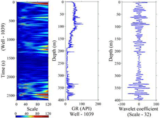
Figure 6Continuous wavelet transform (CWT) using gamma ray signal and the wavelet coefficient at scale 32 of the gamma ray log of well site 1039.
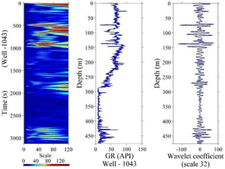
Figure 7Continuous wavelet transform (CWT) using gamma ray signal and the wavelet coefficient at scale 32 of the gamma ray log of well site 1043.
The results obtained from CWT prove the lithological successions. This result is significant in a certain scale range only. Since scale is the inverse of frequency, the small scales correspond to high-frequency components and the large scales correspond to small-frequency components. Wavelet analysis of a signal on a small scale shows the very small changes, which may be associated with noise, and analysis on a large scale shows the outspread view of signal. Multiscale analysis has played an important role in computation of wavelet coefficients (Dimri et al., 2005). The scale is linear in a particular range determined by log(var(coefficients)) versus log(scale) as shown in Fig. 5.
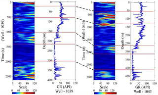
Figure 8Lithology identification using the gamma ray log of well sites 1039 and 1043 by the lines drawn on the scalogram, and the subduction zone in the areas obtained from the seismic-migration section.
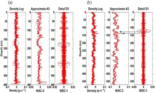
Figure 9(a) Discrete detailed and approximate coefficients; spikes obtained in detailed coefficients represent the possible fracture zone at well site 1039. (b) The discrete detailed and approximate coefficients; the spikes obtained in detailed coefficients represent the possible fracture zone at well site 1043.
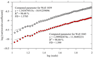
Figure 10Variance of wavelet coefficients versus scale of density log of well sites 1039 and 1043, which show consistent holder exponent and fractal-dimension values, indicating that the wells contain a similar sedimentary environment.
Those stratigraphic interfaces at site 1039 (Fig. 6) that also appear at site 1043 were analysed by CWT (Fig. 7) after having disruptions in the middle. It is observed that the sedimentary successions at site 1039 over the subducted Cocos Plate continue through site 1043 without any disruption situated over the overriding Caribbean Plate. The locations of the wells and the continuity of the sedimentary successions existing at both sites were traced by the correlation of the wavelet scalogram (Fig. 8). The left side of Fig. 8 (site 1039) shows the upper sedimentary succession of 20 m thickness, which consists of dark olive green diatomaceous ooze with an ash layer, and a second sedimentary layer of 64 m thickness (20–84 m), which consists of dark olive green diatomaceous ooze with the absence of ash of graded sand. The third sedimentary formation of 76 m thickness (84–160 m) is distinguished by dark olive grey silty clay with an ash layer downward with increasing calcareous clay and decreasing biogenic sediments, and the fourth layer of 50 m thickness (160–210 m) is rich in ivory-coloured siliceous nannofossil ooze interbedded with calcareous clay. Finally the fourth sedimentary layer varies from 210 to 378 m, consisting of nannofossil ooze with a minor ash layer and increasing interbedded siliceous ooze (Expedition 308 Scientists, 2005). On the right side of the Fig. 8 (site 1043), the thickness of the sedimentary succession above the décollement is 60 m, belonging to the overriding plate, which mainly consists of volcanic ash and minor interbedding of silt and sand. The upper sedimentary layer of well 1039 is partially present in well 1043, while the second layer of well 1039 is present and ranges in depth from 60 to 130 m of well 1043. The third and fourth layers mentioned in well 1039 are also identified in well 1043, and these depth ranges are 130–260 and 260–310 m, respectively. Thus the analyses suggest that the Cocos Plate is being subducted under the Caribbean Plate.
In order to identify the presence of fractures locations, the DWT was applied to the density log of both well 1039 and well 1043 as shown in Fig. 9. According to Sahimi and Hashemi (2001), the DWT gives the scale of WDC that depends on the log signals and smaller fractures which can be significantly seen. If the scale of WDC becomes large, a single fracture or a number of small-scale WDCs indicate series of microfractures. The various scales of WDC at both sites of log signals provide different porosity and fractures at various depths, which is highlighted by circles in Fig. 9a and b.
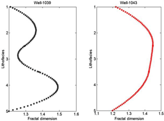
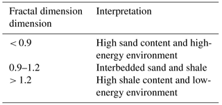
Apart from this, FD values of sedimentary successions identified by CWT were computed as shown in Table 1. The FD values vary from 1.21 to 1.49 at well site 1039 and 1.20 to 1.44 at well site 1043. The coefficient of determination (R2 in percent) is also calculated for both wells. We observed the FD and R2 values of both the wells; the sandy layer is the transitional change between the sandy shale and shaly sandstone due to variation in FD values, and this variation corresponds to a gradual transition between different sedimentary environments here. Hence, the FD values can be used as a well log attribute. Here the FD values are greater than 1.2, which may emphasize the presence of high shale content and low-energy environments in the depth range 210–330 m and 315–430 m in the presence of sandstone over the well sites 1039 and 1043, respectively (Fig. 10 and 11). López and Aldana (2007) have given an explanation for the waveform classifier at the Oritupano-A Field, Venezuela, using wavelet-based fractal analysis as shown in Table 2. In spite of the presence of sandstone, the FD values exceed 1.2, indicating the dominance of shale content, and these values are found to be inconsistent with reference site 1039 and site 1043. The observations are also made from Table 1; the FD values 1.36–1.26 at site 1039 and 1.43–1.44 at site 1043 in the depth range of 80–210 and 130–315 m, respectively, have different values while having the same litho-units (Fig. 8). These particular litho-units may suggest the presence of fracture zones.
In this paper, CWT for identification of lithofacies and DWT for the identification of the fracture zones were applied using well log data taken from two different well sites (1039 and 1043) of the Costa Rica convergent margin, Central America. The CWT analysis provides four major sedimentary lithofacies from the Holocene to the Pleistocene: (i) shale with interbedded ash, (ii) shaly sandstone, (iii) sandy shale with interbedded ash, and (iv) sandstone and the last gabbroic sill from the late Pleistocene to middle Miocene. The traced CWT wavelet scalogram of both well sites 1039 and 1043 shows the continuity of the sedimentary succession. This confirms that the Cocos Plate is being subducted under the Caribbean Plate. Apart from that, one of new techniques, WBFA, was applied on every sedimentary layer, and fractal-dimension (FD) values were calculated, revealing that the second and third successions have high FD values, whereas the first and fourth successions have low FD values. These high values may be due to the presence of abundant shale content and low-energy environments.
The data were taken for study from the public-domain Integrated Ocean Drilling Program (IODP) site.
The authors declare that they have no conflict of interest.
The authors are thankful to the associate editor and both anonymous reviewers
for constructing critical comments to improve our manuscript. One of the
authors, Rahul Prajapati, thanks IIT(ISM) Dhanbad for providing financial
support to continue the research work.
Edited by: Mikko Syrjäsuo
Reviewed by: three anonymous referees
Bansal, A. R., Gabriel, G., and Dimri, V. P.: Power law distribution of susceptibility and density and its relation to seismic properties: An example from the German Continental Deep Drilling Program (KTB), J. Appl. Geophys., 72, 123–128, 2010.
Brown, R. A.: Interpretation of three-dimensional seismic data, 6th Edn., American Association of Petroleum Geologists (AAPG), 540 pp., 2004.
Case, J. E. and Holcombe, T. L.: Geologic – tectonic map of Caribbean region: US geological survey publication, USGS, 1980.
Chandrasekhar, E. and Rao, E. V.: Wavelet Analysis of geophysical welllog data of Bombay Offshore Basin, India, Math. Geosci., 44, 901–928, 2012.
Coconi-Morales, E., Ronquillo-Jarillo, G., and Campos-Enríquez, J. O.: Multi-scale analysis of welllogging data in petrophysical and stratigraphic correlation, Geofísica International, 49, 55–67, 2010.
Dashtian, H., Jafari, Z., Lai, K., Sahimi, M., and Masihi, M.: Analysis of cross correlation between well logs of hydrocarbon reservoirs, Transport Porous Med., 90, 445–464, 2011.
Daubechies, I.: The wavelet transform time-frequency localization and signal analysis, IEEE T. Inform. Theory, 36, 961–1005, 1990.
Daubechies, I.: Ten lectures on wavelets, J. Acoust. Soc. Am., 93, 1671, https://doi.org/10.1121/1.406784, 1992.
Dimri, V. P., Vedanti, N., and Chattopadhyay, S.: Fractal analysis of aftershock sequence of the Bhuj earthquake: A wavelet-based approach, Curr. Sci. India, 88, 4 pp., 2005.
Expedition 308 Scientists: Gulf of Mexico Hhydrogeology – Overpressure and fluid flow processes in the deepwater Gulf of Mexico: slope stability, seeps, and shallow-water flow, IODP Prel. Rept., 308, https://doi.org/10.2204/iodp.pr.308.2005, 2005.
Fedi, M.: Global and local Multiscale Analysis of Magnetic Susceptibility Data, Pure Appl. Geophys., 160, 2339–2417, 2003.
Integrated Ocean Drilling Program (IODP) site, Prel. 308, https://doi.org/10.2204/iodp.pr.308.2005 (last access; May 2018), 2005.
Javid, M. and Tokhmechi, B.: Formation interface detection using Gamma Ray log: A novel approach, Journal of Mining and Environment, 3, 41–50, 2012.
Li, J. T., Yu, J. F., and Li, Z. X.: The demarcating of Stratigraphic sequence based on wavelet transform of well-logging data, Coal Geology & Exploration, 32, 48–50, 2004.
Liu, H. and Jian, Z.: Wavelet Transform of geophysical well logging signal and Its application to sequence division, 3rd International Congress on Image and Signal Processing, Yantai, China, 16–18 October 2010, https://doi.org/10.1109/CISP.2010.5646751, 2010.
López, M. and Aldana, M.: Facies recognition using wavelet based fractal analysis and waveform classifier at the Oritupano-A Field, Venezuela, Nonlin. Processes Geophys., 14, 325–335, https://doi.org/10.5194/npg-14-325-2007, 2007.
Mansinha, L., Stockwell, R. G., Lowe, R., Eramian, M., and Schincariol, R. A.: Local S-spectrum analysis of 1-D and 2-D data, Phys. Earth Planet. In., 103, 329–336, 1997.
Moritz, E., Bornhold, S., Westphal, H., and Meschede, M.: Neural network interpretation of LWD data (ODP Leg 170) confirms complete sediment subduction at the Costa Rica convergent margin, Earth Planet. Sc. Lett., 174, 301–312, 2000.
Pan, S., Hsieh, B., Lu, M., and Lin, Z.: Identification of stratigraphic formation interfaces using wavelet and Fourier transforms, Comput. Geosci., 34, 77–92, 2008.
Pinnegar, C. R. and Mansinha, L.: The S-transform with window of arbitrary and varying shape, Geophysics, 68, 381–385, 2003.
Pinnegar, C. R. and Mansinha, L.: Time-local Fourier analysis with a scalable, phase-modulated analyzing function: TheS-transform with a complex window, Signal Process., 84, 1167–1176, 2004.
Sahimi, M. and Hashemi, M.: Wavelet identification of the spatial distribution of fractures, Geophys. Res. Lett., 28, 611–614, 2001.
Singh, U. K.: Fuzzy Inference System for identification of lithologs off Prydz Bay, East Antarctica, J. Appl. Geophys., 75, 687–698, 2011.
Singh, U. K., Singh, D. K., and Singh, H.: Application of Neurofuzzy Pattern Recognition Method in Borehole Geophysics, Acta Geod. Geophys. Hu., 45, 417–425, 2010.
Stockwell, R. G.: Why use the S-Transform?, AMS Pseudo-differential operators: partial differential equations and time-frequency analysis, 52, 279–309, 2007.
Stockwell, R. G., Mansinha, L., and Lowe, R. P.: Localization of complex spectrum: The S Transform, IEEE T. Signal Proces., 44, 998–1001, 1996.
Tokhmechi, B., Memarian, H., Rasouli, V., Ahmadi, N. H., and Moshiri, B.: Fracture zones detection using wavelet decomposition of water saturation log, J. Petrol. Sci. Eng., 69, 129–138, 2009a.
Tokhmechi, B., Memarian, H., Ahmadi, N. H., and Moshiri, B.: A novel approach for fracture Zone detection using petrophysical logs, J. Geophys. Eng., 6, 365–373, 2009b.
Yue, W. Z., Tao, G., and Liu, Z. W.: Identifying reservoir fluids by wavelet transform of well logs, in: Proceedings of the SPE Asia Pacific Oil and Gas Conference and Exhibition, Perth, Australia, SPE-88559-PA, 2004.
Zhang, X.-F., Pan, B.-Z., Wang, F., and Han, X.: A study of wavelet transforms applied for fracture identification and fracture density evaluation, Appl. Geophys., 8, 164–169, 2011.


