the Creative Commons Attribution 4.0 License.
the Creative Commons Attribution 4.0 License.
 | 15 Oct 2018
A hybrid fluxgate and search coil magnetometer concept using a racetrack core
B. Barry Narod
David K. Milling
Ian R. Mann
David Barona
George B. Hospodarsky
A proof-of-concept hybrid magnetometer is presented, which simultaneously operates as both a fluxgate and a search coil, allowing it to sense the magnetic field from DC to 2 kHz using a single sensor. Historically, such measurements would normally require two dedicated instruments, and each would typically require deployment on its own dedicated boom as the instruments mutually interfere. A racetrack fluxgate core combined with a long solenoidal sense winding is shown to be moderately effective as a search coil magnetometer, and the search coil effect can be captured without introducing significant hardware complexity beyond what is already present in a typical fluxgate instrument. Several methods of optimising the search coil action of the hybrid instrument are compared with the best method providing sensitivity and noise performance between comparably sized traditional air-core and solid-core search coil instruments. This hybrid sensor topology should miniaturise to platforms such as CubeSats for which multiple boom-mounted instruments are generally impractical, so a single hybrid instrument providing modest, but scientifically useful, sensitivity from DC to kHz frequencies would be beneficial.
- Article
(5510 KB) - Full-text XML
- BibTeX
- EndNote


Space science missions (e.g. Angelopoulos, 2009; Kessel et al., 2013) often need two magnetic field instruments – a search coil magnetometer for high ( Hz) frequencies (Fig. 1a) and a fluxgate for the static field and low frequencies (Fig. 1b). These two instruments will interfere with each other if they are located too close together. The search coil can detect the drive signal in the fluxgate magnetometer, and the ferromagnetic core typically used for magnetic gain in the search coil distorts the field measured by the fluxgate. The two instruments are therefore frequently mounted on separate deployable booms, which affects spacecraft control and can impinge on the field of view of other instruments.
Figure 1(a) THEMIS search coil showing typical long cylindrical sense coils – credit NASA. (b) Fluxgate sensor showing compact rectangular sense coils – from Wallis et al. (2015).
Search coil magnetometers and fluxgate magnetometers (Hospodarsky, 2016; Primdahl, 1979) both sense the local magnetic field through the electromagnetic force (EMF) induced by changing magnetic flux Φ described by the generalised induction equation (Eq. 1) for a coil of wire of N turns and area A, in a field H, with a ferromagnetic core of relative permeability, μr:
Search coils measure the voltage induced due to the changing magnetic field , while fluxgates measure the voltage induced by changing the relative permeability of a periodically saturating ferromagnetic core . Search coils typically have no single dominant noise source, so compact space instruments tend to use a long ferromagnetic core for magnetic gain and tens of thousands of turns of wire to increase sensitivity. Fluxgate noise is typically dominated by the magnetic noise of the ferromagnetic core, so only small, compact flat windings of a few hundred turns are required to avoid the coil being a significant noise source. This paper describes a proof-of-concept hybrid magnetometer which explores whether both the search coil and fluxgate sense mechanisms can be simultaneously extracted from a common sense winding.
Several authors (Gordon et al., 1965; Hinnrichs et al., 2000, 2001; Ripka, 1990, 1993, 2000) have explored using long racetrack (oval) cores (Fig. 2d) instead of circular (Fig. 2a) ring cores. The racetrack geometry mimics the long cylindrical cores often used in search coil sensors (Fig. 2c) and is compatible with similar long solenoidal sense windings (Fig. 2b). The fluxgate action has been demonstrated to have bandwidth to at least 3 kHz (Ioan et al., 1996; Miles et al., 2013; Primdahl et al., 1994). However, since fluxgate sensitivity is essentially flat with frequency and search coil gain tends to increase with frequency until the self-resonance of the coil, search coil magnetometers tend to provide better sensitivity above a few tens of Hz.
The complementarity of the two sensor technologies has led several authors to investigate creating hybrid instruments which can exploit both the fluxgate and the search coil effects. Two groups (Han et al., 2012; Shi et al., 2017) are developing hybrid instruments by embedding a fluxgate within the hollow core of a search coil and electrically fusing the outputs. This same technique can be used for other DC magnetometer technologies, such as by embedding a Hall sensor at the centre of a search coil core (Leroy et al., 2008). Ripka et al. (1995) investigated whether the feedback coil in a fluxgate could also be used as a search coil magnetometer. This paper extends that concept by changing the geometry of the fluxgate sensor to mimic that of a search coil such that both effects can be extracted from a common sense winding. Zhang et al. (2010) used a similar sensor design but interleaved at ∼1 s intervals and switched off the fluxgate excitation when operating the search coil. The paper also examines the search coil signal extraction to see if it can be improved by interleaving its capture with the fluxgate action on the timescale of the excitation of the core.
Figure 2(a) Traditional 25.4 mm fluxgate ring core. (b) A solenoidal sense winding. (c) Solid Permalloy core representative of search coil magnetometers. (d) Racetrack fluxgate core similar in geometry to that used in a search coil.
Figure 3Racetrack foil bobbin used in the sensor for the hybrid magnetometer (units in inches).
Fluxgate magnetometer cores are periodically driven into magnetic saturation to modulate the local magnetic field. The fluxgate signal is generated by the core's changing permeability as it enters and exits magnetic saturation. However, because the core is typically driven in resonance (Acuna, 1974) with short-period high-amplitude current spikes, the core is in deep saturation less than 25 % of the time. The solenoidal sense coil should act as a solid-core search coil when the core is unsaturated, an air-core search coil when the core is in saturation, and a fluxgate while the core is entering or leaving saturation. If the saturation of the core and the sampling of the sense coil are synchronised, the different sensor effects should be separable using digital signal processing, allowing the sensitivity and noise floor of the two effects to be compared. Utilising both the search coil and fluxgate mechanisms may provide a way to combine the flat frequency response of the fluxgate with the increasing gain with frequency of the search coil to eventually span a range from DC to >10 kHz in a single instrument.
The racetrack cores presented here were produced as part of a larger project to apply the theory of Narod (2014) to produce lower-noise fluxgate cores and cores in non-traditional sizes and geometries (Miles et al., 2016). Most of that work used 25.4 mm circular ring core (Fig. 2a) but a few racetrack cores (Fig. 2d) were manufactured to explore the role of geometry in core noise. The racetrack core is formed on an Inconel bobbin with an 82.5 mm long axis, a 9.65 mm short axis, and a 1.65 mm channel on its outside surface (Fig. 3). Three layers of a 100 µm foil are spiral wrapped into the groove and attached with spot welds. The foil was manufactured by successive cold-rolling of a 6.0–81.3 molybdenum–nickel Permalloy, which was then coated with an insulating layer of magnesium oxide. The assembled bobbin and foil were heat-treated for 4 h at 1150 ∘C in a reducing atmosphere of 5 % hydrogen in 95 % argon.
The drive winding for the racetrack was 677 turns of AWG 32 enamelled wire wound toroidally. The sense winding was arbitrarily chosen to be 2247 solenoidal turns of AWG 37 enamelled wire in four layers on a fused quartz tube with an outer diameter of 15.4 mm. The length of the solenoidal winding was roughly matched to the long axes of the racetrack core. A Permalloy rod of 7 mm diameter and 95 mm length was used to compare the hybrid magnetometer sensitivity to that of the same sense winding operated as a traditional search coil with a solid core.
Figure 4 shows a block diagram of the set-up used to explore the hybrid magnetometer concept. The magnetometer is operated open loop, without magnetic feedback, to examine the natural response of the sensor. A field-programmable gate array (FPGA) is used to send 2.5 kHz alternating polarity power amplified (PA) current pulses (Idrive) into the toroidal drive winding to periodically saturate the racetrack core. The solenoidal sense winding is used in the short-circuit–current-output configuration such that the changing magnetic flux due to the external field (Hsense) experienced by the coil induces a current, ISense. This current is converted to an equivalent voltage (I/V), passed through a weak single-pole low-pass anti-alias filter with a −3 dB point at 5 kHz (LPF) and then synchronously digitised (ADC) in phase with the drive by the FPGA.
Figure 4Schematic of the test set-up showing the driven sensor, analogue processing, and parallel digital processing paths of common sampled data for fluxgate and search coil reconstruction. Adapted from Miles et al. (2013).
Digital signal processing is used to separate the search coil and fluxgate signals in the raw ADC stream. The fluxgate path follows a classic second harmonic design; the data are band-pass filtered (BP) at the second harmonic, run through a phase-sensitive inverter (PSI), integrated (INT), and then decimated (DEC) to 400 sps. In the search coil path, the raw data are also sliced into four separate streams corresponding to different phases of the core magnetisation cycles (Slice) and each has a static offset removed (Offset) and is then low-pass filtered (LPF) and decimated (DEC) to 2500 sps search coil data streams.
Figure 5 shows a fast Fourier transform of the raw ADC samples captured from the hybrid sensor driven as a fluxgate and exposed to a 100 nT sinusoidal test signal. The test signal is visible at 100 Hz baseband (Fig. 5a) via the search coil action. The fluxgate drive is clear at 2.5 kHz (Fig. 5b) and 7.5 kHz (Fig. 5d), and the fluxgate signal appears at the 5 kHz second harmonic (Fig. 5c). The test signal appears in the inset through the fluxgate action as the lower 4.9 kHz (Fig. 5e) and upper 5.1 kHz (Fig. 5f) sidebands analogous to amplitude modulation radio encoding (Hinnrichs et al., 2001; Miles et al., 2013). All signals are well separated in frequency space, suggesting that they can likely be isolated and reconstructed using a low-pass filter (red) for the search coil effect and a band-pass filter (green) for the fluxgate.
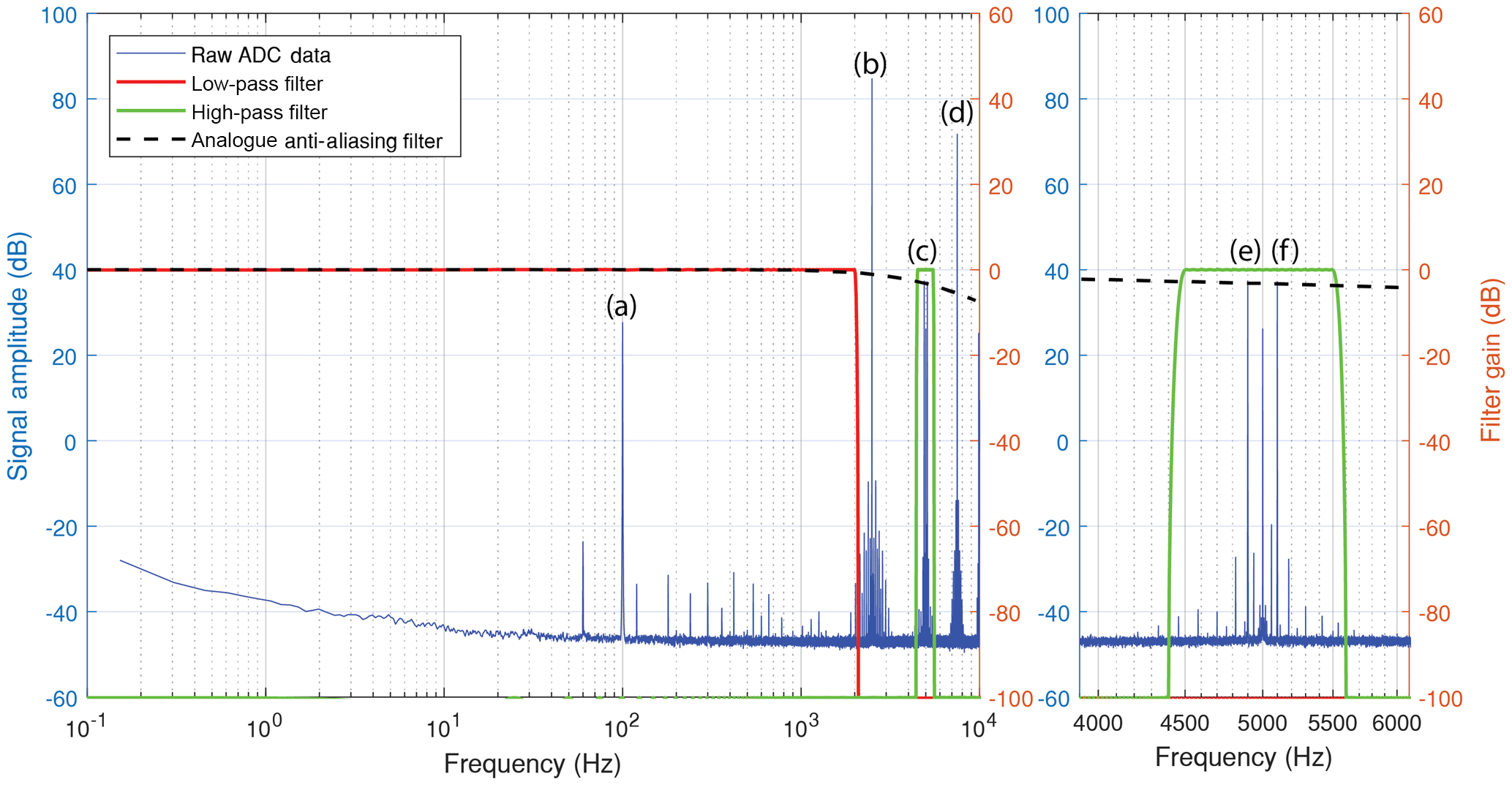
Figure 5Fast Fourier transform of raw ADC data with 100 nT 100 Hz magnetic test signal. (a) Baseband test signal at 100 Hz. Fluxgate drive signal at (b) 2500 Hz and (d) 7500 Hz. (c) Second harmonic fluxgate signal at 5000 Hz. Fluxgate signal sidebands at (e) 4900 and (f) 5100 Hz. Note that all signals are well separated in frequency space.
The racetrack core was driven at 2.5 kHz using the resonant drive circuit described in Miles et al. (2016). The current circulating in the toroidal drive winding was measured using a 0.1 Ohm current snoop resistor and is shown in Fig. 6a. Note that, due to the tuning of the resonant drive circuit, the current pulses are engineered to have a high amplitude capable of pushing the racetrack core into deep magnetic saturation but have a short duration. This low-duty cycle reduces power consumption and has the core in deep saturation less than 25 % of the time. The current output of the sense winding, transformed into an equivalent voltage and anti-alias filtered, is shown in Fig. 6b. Figure 6a and b were captured at high cadence using a bench-top oscilloscope. The phase offset between the drive current pulses (Fig. 6a) and the sensor output waveform (Fig. 6b) is believed to result from the RLC behaviour of the sense coil and preamp.
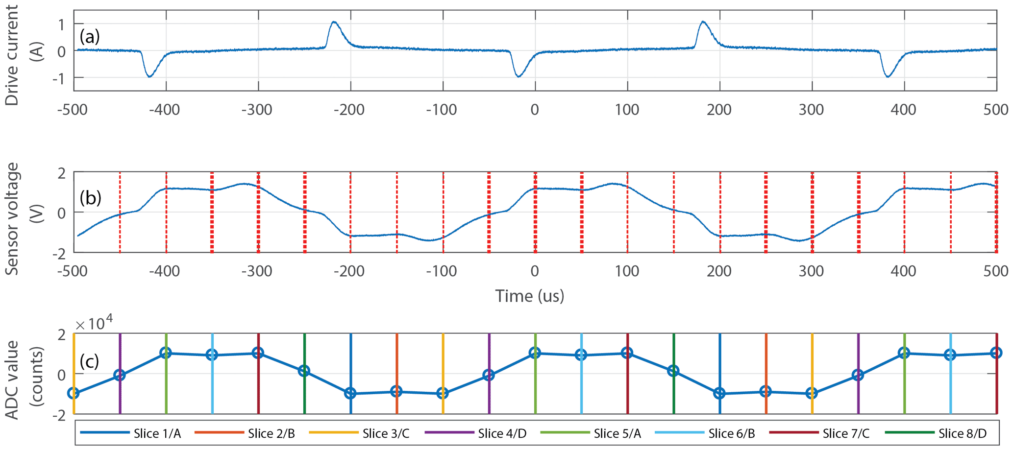
Figure 6(a) Drive current into the racetrack core. (b) Analogue output of the long solenoidal sense winding and ADC sampling points. (c) Digitised sensor output with eight colour-coded phase “slices”.
An equivalent representative time series, captured through the ADC, is shown in Fig. 6c. The ADC samples at 20 000 sps or 4 times faster than required for a classic second harmonic direct digitised fluxgate. The vertical lines show the trigger points of the ADC and are colour coded to indicate how the data are “sliced” into eight time series corresponding to the eight different phases in the magnetisation loop of the core as shown in Table 1.
Table 1Correspondence of slice number and core saturation state.
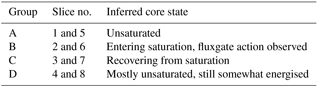
Slices 2/B and 6/B contain the majority of the fluxgate action produced by the current pulses forcing the core into saturation, during which time the sensor should function like an air-core search coil. Outside of deep saturation the sensor should function like a traditional high-permeability core search coil albeit with an unusually low-mass core. While the core is recovering from saturation, it is likely still partially energised and will exhibit Barkhausen noise. This stream of raw samples will be reconstructed as both a fluxgate and search coil magnetometer below.
If it were somehow possible to sample the magnetic field at the core directly then these saturation states could be accessed independently and without interference. However, since the magnetic field is accessed via its induction of current and/or voltage in the sense coil, the signal from the different magnetic states must pass through the RLC filter formed by the sense winding, the preamplifier, the anti-aliasing filter, and the analogue-to-digital converter. Each of these stages has a transfer function which will, to varying degrees, blend the different saturation states unless the combined phase delay of all the stages is below half a sample, which does not appear to be the case here. Consequently, the various saturation states are likely somewhat mixed and cannot be separated perfectly. Nevertheless, we will explore treating the various saturation states separately to see if any performance benefit can be gained.
Figure 7 shows the power spectral density (PSD) of the ADC stream with a 100 nT sinusoid at 100 Hz applied to the sensor. Black shows all ADC samples and the colours show demodulation into eight separate streams corresponding to Slices 1–8 in Fig. 6 and the eight phases of the racetrack core magnetisation cycle.
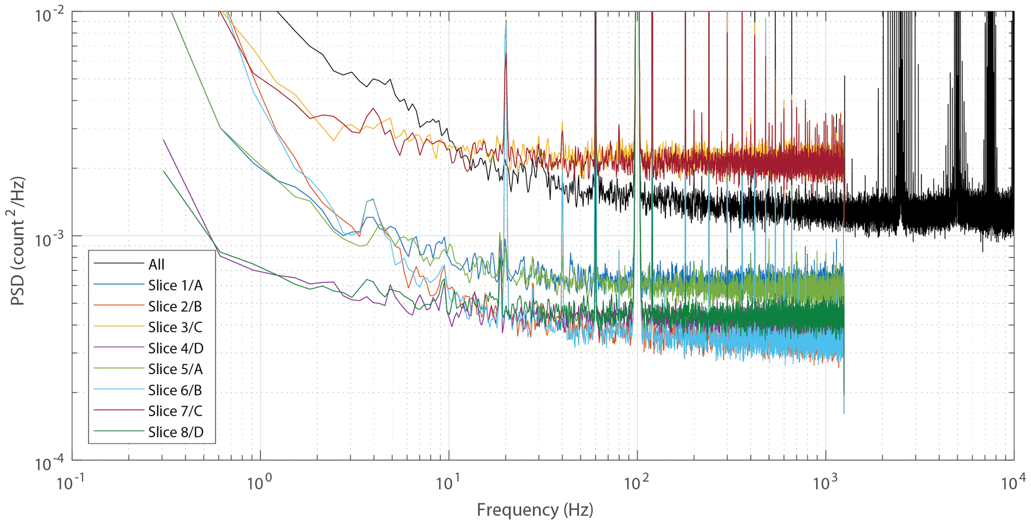
Figure 7Power spectral density (PSD) of the raw ADC values (black) and demodulated into eight slices (colours) corresponding to the eight phases of the racetrack core magnetisation cycle.
The nine spectra have been normalised such that the 100 Hz test signal has a common amplitude. As expected, the eight slices form four pairs corresponding to the equivalent places in the positive and negative phases of the drive signal. For the remainder of this paper the data will be sliced into four streams made up as A (Slices 1 and 5), B (Slices 2 and 6), C (Slices 3 and 7), and D (Slices 4 and 8) as shown in Table 1. Slice B contains the majority of the fluxgate action, so it seems plausible that, during the following Slice C, the core is still somewhat energised. As the core returns to its unsaturated state, Barkhausen jumps may be contributing to the high noise floor observed in Slice C.
Note the presence of narrow spectral content at 20, 40, and 80 Hz in the sliced spectra which are not present on the spectra generated from the raw ADC samples. This is consistent with spectral folding, which would be expected as the raw ADC samples are not band limited via an anti-aliasing filter before the slicing as that would further mix the core saturation states. This will have the practical effect of folding signals in the 2.5–10 kHz band, mostly associated with the fluxgate mechanism, down into the search coil bandwidth.
Figure 8 shows the steps in reconstructing the fluxgate signal. The fluxgate action acts analogous to amplitude modulation (AM) radio encoding. A natural signal at frequency fo is modulated to two sidebands around the second harmonic of the drive signal 2f±fo. The raw ADC samples (Fig. 8a) are therefore band-pass filtered (Fig. 8b) at the second harmonic of the drive plus or minus the desired bandwidth of the fluxgate path (5000±500 Hz) to isolate the fluxgate signal from the search coil signal at baseband and the harmonics of the drive signal (2500 and 7500 Hz, respectively).
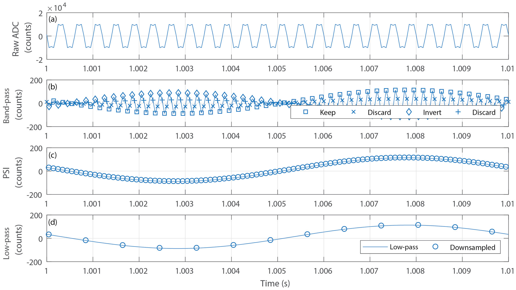
Figure 8(a) Raw ADC samples. (b) Band-pass-filtered samples showing which samples are kept, inverted, and dropped in the phase-sensitive inverter. (c) Reconstructed test signal. (d) Averaged and decimated fluxgate stream.
The band-pass-filtered data (Fig. 8b) manifest the 100 Hz magnetic test signal as the envelope of the 5 kHz (2f) oscillation. This is demodulated as marked in Fig. 8b. Every other extremum point is inverted and the intermediary points are discarded. The intermediary points can be inverted and included, although they introduce a significant 2f oscillation. However, doing so was found to decrease the signal-to-noise ratio. The phase-sensitive inversion restores the sinusoidal test signal (Fig. 8c), which is then averaged and decimated to produce a 1000 sps fluxgate stream shown as the circles in Fig. 8d.
Figure 9a shows that the sensitivity of the fluxgate path varies by less than 0.5 dB from DC to 100 Hz (normalised to 0 dB at DC) and 3 dB from DC to 500 Hz.
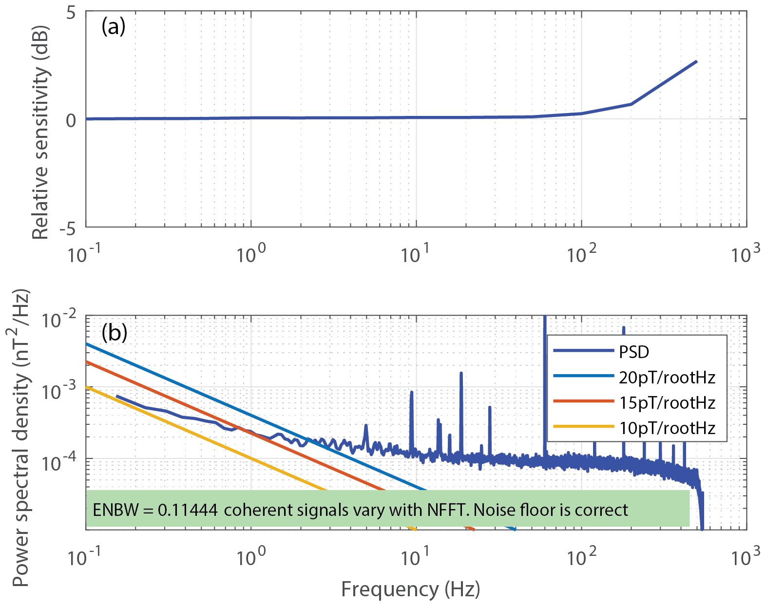
Figure 9(a) Variation of the fluxgate sensitivity with frequency. (b) Power spectral density (PSD) noise floor of the fluxgate path showing ∼15 pT Hz at 1 Hz.
Figure 9b shows the power spectral density (PSD) noise floor of the fluxgate path calculated with data taken while the sensor was in a three-layer Mumetal magnetic shield. The core achieves a modest ∼15 pT Hz at 1 Hz. The same foil in roughly the same quantity with the same heat treatment achieves ∼6 pT Hz at 1 Hz when wound onto a 25.4 mm circular ring core. Other authors (e.g. Hinnrichs et al., 2001; Ripka, 1993) have achieved good noise and sensitivity using racetrack geometry cores, so we interpret these results to suggest that something about the manufacture or drive of the racetrack core presented here is not yet optimised. This is beyond the scope of this paper and is the subject of ongoing work.
Figure 10 shows the steps in the reconstruction of the search coil signals. The raw ADC values (Fig. 10a) are low-pass filtered at 1000 Hz to remove the fluxgate drive, creating the “all samples” trace in Fig. 10b, and then decimated (Fig. 10c). The raw ADC samples are also sliced into four time series (Slices A–D) corresponding to the four phases of the magnetisation cycle of the core, low-pass filtered at 1000 Hz, and independently detrended to remove the static offset caused by that phase of the magnetisation cycle (Fig. 10b).
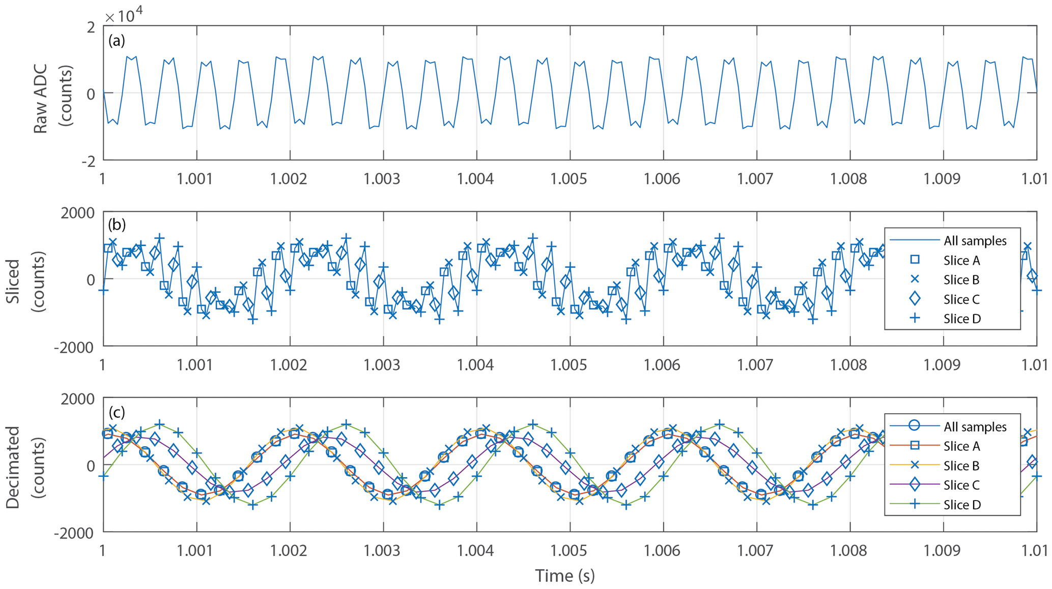
Figure 10Reconstruction of the search coil signal from (a) raw ADC data to (b) sliced, low-pass filtered, and detrended and (c) decimated to common cadence.
The five time series show the 500 Hz magnetic test signal at significantly different amplitudes. This is consistent with the general trend shown in Fig. 7 in which each digitisation offset captures a different degree of core saturation and hence a different magnetic gain. Figure 11a compares the sensitivity (nT bit−1) as a function of frequency for each of the hybrid search coil time series and for the same sense coil used as a traditional search coil. The sense coil was operated as an air core, with a solid Mumetal core, and with the racetrack core in unsaturated and continually saturated states. As expected, all configurations perform similarly above ∼2 kHz where the coil is expected to dominate. At lower frequencies, the effect of the magnetic gain of the core becomes more significant and, below ∼100 Hz, the gain of the five hybrid search coil traces becomes unexpectedly flat with frequency. The 500 Hz test signal was selected as it illustrates the region where the magnetic gain of the core is significant to the search coil effect – above frequencies where the fluxgate effect dominates and below frequencies where the coil response dominates.
Between ∼200 and ∼2000 Hz the ordering and trend of the sensitivities matches intuitive expectations. The air core and the continually saturated racetrack core provide comparable gain. At the other extreme, the unsaturated racetrack provides about half the gain of the solid Mumetal rod. The five hybrid search coil reconstructions lie between these with the unsliced data providing the lowest sensitivity.
The constant gain below ∼40 Hz for the hybrid search coil reconstructions appears to be a frequency folding effect caused by insufficient anti-aliasing before digitisation. The racetrack core is driven at 2500 Hz, so the fluxgate modulation will manifest as sidebands around the even harmonics at 5000, 10 000, 20 000 Hz, etc. A 1 Hz magnetic test signal will therefore create a sideband at 20 001 Hz (eight harmonic). The sensor is sampled at 20 000 sps, creating a 10 000 Hz Nyquist frequency. Therefore, the 20 001 Hz sideband will frequency fold over the Nyquist frequency and 0 Hz down to an aliased 1 Hz, which will dominate compared to the small sensitivity of the search coil at low frequencies.

Figure 11(a) Comparison of frequency-dependent gain for various hybrid and standard search coil configurations. (b) Comparison of power spectral density noise floor for the various search coil configurations. The constant gain and noise at low frequencies is believed to be an aliasing artefact.
A standard figure of merit for search coil performance is the power spectral density noise floor of the instrument (Fig. 11b) using quiet data taken inside a magnetic shield normalised by the frequency-dependent gain. As expected, the solid Mumetal core provides the lowest noise, followed by the unsaturated racetrack core. The air core and the continuously saturated racetrack core provide the poorest result. The unsliced hybrid search coil path performs between the solid- and air-core limits as expected. However, the sliced hybrid search coil path performs significantly worse than the air-core search coil above ∼500 Hz where the search coil gain can be accurately measured without interference from the aliased fluxgate signal.
In the frequency range of ∼50–250 Hz, where the search coil gains can be accurately measured but are not yet dominated by the sense coil, the gain ratio between the unsaturated coil and the saturated coil is approximately 3.6. However, the ratio of noise levels at 100 Hz for the unsliced hybrid search coil and the unsaturated racetrack core is larger, approximately 5.3. The noise level of the hybrid search coil therefore cannot be entirely due to lower magnetic gain. This implies the presence of an additional magnetic noise source – potentially Barkhausen jumps due to the excitation of the core.
Figure 12 compares the sensitivity and noise floor obtained from the hybrid instrument using both the fluxgate reconstruction and the unsliced search coil reconstruction. The fluxgate reconstruction essentially provides flat sensitivity with frequency (Fig. 12a) and a superior noise floor at low frequencies (Fig. 12b). As expected, the search coil reconstruction is much more frequency dependent and provides modestly superior gain and noise above ∼1 kHz. Figure 12 also shows the performance of the same sense coil operated as a traditional search coil with a solid Mumetal core to illustrate how much search coil performance is sacrificed by operating it as a hybrid sensor.
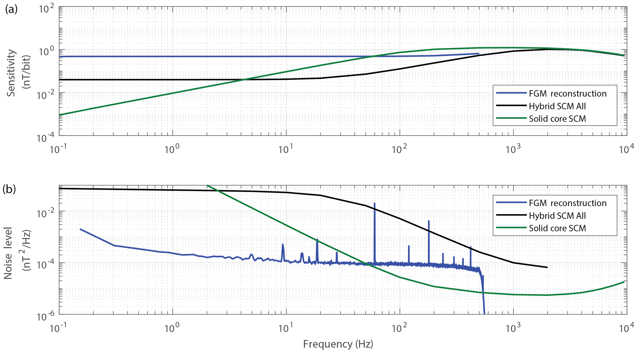
Figure 12(a) The fluxgate and search coil reconstructions of the hybrid magnetometer data compared to the same sense winding operated as a conventional search coil with a solid core. (a) Frequency-dependent sensitivity and (b) instrumental noise floor. The flat response at low frequencies for the search coil reconstruction of the hybrid magnetometer is believed to be an aliasing artefact rather than true instrumental response.
Developing a complete vector space-flight sensor based on the proof-of-concept work described here will require addressing several design issues: the addition of magnetic feedback to linearise and extend the range of the fluxgate path, robust and highly orthogonal mounting of three sensor axes, and likely the development of real-time processing firmware for the search coil and fluxgate paths to avoid telemetering the raw digitised data.
All data presented here were taken with the instrument operating in open loop. For most practical applications, magnetic feedback will be required to extend the magnetic range, linearise the instrument, and potentially to provide temperature compensation. In a primarily digital design, such as that presented here, this magnetic feedback is typically accomplished using a digital-to-analogue converter to force current either into the sense winding or into a separate feedback winding and drive the field in the sensor towards zero. The range of the instrument is then set by the maximum amount of feedback current, the instrument's linearity is primarily dependent on the feedback circuit, and feedback current can be made temperature sensitive to compensate for changes in sensor geometry (Acuña et al., 1978; Miles et al., 2017). Updates to the fluxgate feedback will undoubtedly impact the search coil action, particularly in instruments with high-bandwidth feedback used either to maximise instrument linearity or to track rapid changes in the magnetic field, such as on spinning platforms. Characterisation, modelling, and compensation will be required to correct for the dynamic behaviour of the magnetic feedback. Although compensating for the dynamic behaviour of magnetic feedback is required in most fluxgate magnetometers, the additional search coil action in the hybrid magnetometer is likely to be particularly sensitive, which will drive instrument complexity.
Fluxgate and search coil magnetometers build up a vector magnetic field measurement from three nominally orthogonal projections. Small misalignment of these axes can be mitigated using an orthogonality matrix correction. However, a secondary effect which can be difficult to characterise and calibrate out is the potential for cross-talk between the channels. The presence of a ferromagnetic core and/or magnetic feedback are expected to create cross-talk offsets in the same way as in standard fluxgate or search coil sensors. A potentially trickier issue is whether the broader bandwidth and higher sensitivity of the search coil path will cause it to pick up transients from dynamical fluxgate behaviours such as, in an offsetting instrument, updating the magnetic feedback in one of the other sensor axes. Such effects will need to be carefully characterised and potentially compensated for within the instrument.
The racetrack ring core and the glass-tube-based solenoidal winding used in the proof-of-concept prototype have a mass of 6 and 46 g, respectively. Allowing for some mass optimisation of the sense winding, three sensor axes, and a mount to hold the axes orthogonal, we estimate that a complete vector hybrid sensor based on the current racetrack cores would likely have a mass of ∼250–300 g and extend ∼10 cm in each direction. Extrapolating from the current laboratory electronics, a complete three-channel instrument would likely consume ∼400–500 mW of power during normal operation.
A flight version of the hybrid magnetometer would likely need to implement both fluxgate and search coil reconstruction in onboard processing. An instrument with three channels sampling to 24 resolution at 20 000 sps would require ∼1.4 Mbps of bandwidth for the forward loop, with some lower but non-trivial bandwidth required to telemeter the magnetic feedback applied to each sensor axis. For spacecraft applications with telemetry constraints, this bandwidth could be significantly reduced by processing the raw samples onboard the spacecraft into a lower-cadence fluxgate stream (three channels of 24-bit fluxgate data at 100 sps requires ∼7 kbps) and compressed spectral products, such as averaged spectra or filter banks from the search coil path. This processing could be accomplished either in real time in the FPGA or in software on an embedded computer in the spacecraft.
The presented proof-of-concept instrument demonstrates how a racetrack sensor can be simultaneously operated as both a fluxgate and a search coil magnetometer. The combination of a racetrack fluxgate core and a long solenoidal sense winding is modestly effective as a search coil magnetometer, and the search coil effect can be captured without introducing significant hardware complexity beyond what is already present in a typical fluxgate instrument. The search coil action was found to have significantly different magnetic gain at different phases in the magnetisation cycle of the core. However, slicing the data to use only the phase with the highest magnetic gain produced a higher instrumental noise floor than simply using all samples – potentially due to the mixing of the saturation states by the combined transfer function of the sense winding and electronics. The best hybrid search coil reconstruction performed roughly 4 times better (6 dB), in terms of power spectral density noise floor, than an air core with the same sense winding and roughly 10 times worse (−10 dB) than the same sense winding paired with a comparably sized solid Mumetal core. At present, the noise floor and sensitivity of the hybrid search coil data are only modestly better than the fluxgate data and only at frequencies above ∼1 kHz. In principle, the fluxgate could be operated at higher (kHz) frequencies to provide similar data with only a modest loss in sensitivity. However, since it has been demonstrated that the fluxgate and search coil actions can be extracted separately it may be possible to optimise the search coil behaviour of the sensor to provide high-frequency sensitivity and a noise floor beyond that which is possible with current fluxgate technology.
It seems likely that the number of turns in the sense winding would need to be increased by roughly an order of magnitude, and the preamplifier gain doubled or quadrupled, to provide a search coil performance comparable to that of historical space-based instruments. This proof-of-concept instrument achieves a noise floor of nT2 Hz−1 at 1000 Hz compared to nT2 Hz−1 for the ∼10 cm search coil on MMS and nT2 Hz−1 for the ∼40 cm search coil on the Van Allen Probes (Hospodarsky, 2016). The coil and preamplifier design will need to be coupled with careful optimisation of drive frequency, the self-resonance frequency of the coil, and digitiser resolution to exploit the high search coil gain without exceeding the bandwidth of the analogue electronics or the digitiser. In particular, the self-resonance of the coil should likely be optimised to align with the baseband search coil bandwidth. Combined with a higher-order low-pass anti-alias filter, this should improve the search coil performance while preventing interference between the search coil and fluxgate actions. It remains to be seen if the sensitivities of the two effects in a hybrid instrument can simultaneously be made operationally useful. It is also possible that with sufficiently high instrumental sensitivity we will discover that the search coil action is contaminated by Barkhausen noise, caused by periodically saturating the core, at a level that limits the usefulness of the search coil data. This sensor topology should miniaturise to platforms such as CubeSats for which multiple boom-mounted instruments are generally impractical, so a single hybrid instrument providing even modest sensitivity from DC to 10 kHz could be beneficial.
The bandwidth of the search coil reconstruction is limited by the fluxgate drive frequency. Moving to a thinner Permalloy foil should allow the racetrack core to be efficiently driven at higher frequencies and enable a wider search coil bandwidth. The fluxgate noise floor still seems to be dominated by the magnetic noise of the core, so the number of turns in the sense winding and its self-resonance could likely be optimised with minimal impact on the fluxgate action as long as the bandwidth of the coupled fluxgate drive does not saturate the instrument. Higher-resolution digitisation (>16 bit) will likely be required to achieve a competitive search coil noise level given the large analogue bandwidth necessary to accommodate the raw fluxgate signal. Finally, the noise floor of the hybrid search coil data implies the presence of an additional magnetic noise source, which we speculate may be due to Barkhausen jumps due to excitation of the core. This needs to be confirmed and, if this is the case, thickness, number of layers, and heat treatment should be explored to see if the core can be engineered to de-energise more rapidly.
The data and source code used in the creation of this paper are available from https://doi.org/10.25820/t6pr-1551 (Miles, 2018).
DMM led the experiment, designed and built the experimental apparatus, executed the experiment, analysed the data, and prepared the paper with contributions from all authors. BBN created the magnetic material for the racetrack sensor and designed the heat treatment of the racetrack cores. IRM and DKM helped interpret the fluxgate behaviour of the hybrid instrument. DB designed the racetrack core. GH helped interpret the search coil behaviour of the hybrid instrument.
B. Barry Narod operated Narod Geophysics Ltd., which manufactured fluxgate magnetometers until the company ceased production operation in 2008.
Work on the project was supported by the Canadian Space Agency under contract
9F063-140909/006/MTB. David M. Miles was supported by an NSERC PGSD graduate
scholarship, faculty start-up funding from the University of Iowa, and an Old
Gold Summer Fellowship from the University of Iowa College of Liberal Arts
and Sciences. Ian R. Mann is supported by a Discovery Grant from the Canadian
NSERC. The authors wish to thank Taryn Haluza-DeLay for manufacturing the
solenoidal sense winding and Zoë Dent for attaching the driving winding to
the racetrack core. Miroslaw Ciurzynski manufactured and heat-treated the
racetrack core and provided detailed comments on an early version of this
paper. Andy Kale provided comments on an early version of the experiment.
Joshua Larson provided comments on an early version of this paper. The
authors wish to thank Mark Moldwin and two anonymous reviewers for the
constructive comments on this paper, which significantly contributed to the
understanding and explanation of the impact of slicing the search coil data
and the origin of the noise floor in the hybrid search coil
reconstruction.
Edited by: Valery Korepanov
Reviewed by: Mark Moldwin and two anonymous referees
Acuna, M.: Fluxgate magnetometers for outer planets exploration, IEEE T. Magn., 10, 519–523, https://doi.org/10.1109/TMAG.1974.1058457, 1974.
Acuña, M. H., Scearce, C. S., Seek, J., and Scheifele, J.: The MAGSAT vector magnetometer: A precision fluxgate magnetometer for the measurement of the geomagnetic field, National Aeronautics and Space Administration, 1978.
Angelopoulos, V.: The THEMIS mission, in: The THEMIS Mission, Springer, 5–34, available at: http://link.springer.com/chapter/10.1007/978-0-387-89820-9_2 (last access: 16 September 2016), 2009.
Gordon, D., Lundsten, R., and Chiarodo, R.: Factors affecting the sensitivity of gamma-level ring-core magnetometers, IEEE T. Magn., 1, 330–337, https://doi.org/10.1109/TMAG.1965.1062987, 1965.
Han, F., Harada, S., and Sasada, I.: Fluxgate and Search Coil Hybrid: A Low-Noise Wide-Band Magnetometer, IEEE T. Magn., 48, 3700–3703, https://doi.org/10.1109/TMAG.2012.2196762, 2012.
Hinnrichs, C., Pels, C., and Schilling, M.: Noise and linearity of a fluxgate magnetometer in racetrack geometry, J. Appl. Phys., 87, 7085–7087, https://doi.org/10.1063/1.372939, 2000.
Hinnrichs, C., Stahl, J., Kuchenbrandt, K., and Schilling, M.: Dependence of sensitivity and noise of fluxgate sensors on racetrack geometry, IEEE T. Magn., 37, 1983–1985, https://doi.org/10.1109/20.951028, 2001.
Hospodarsky, G. B.: Spaced-based search coil magnetometers, J. Geophys. Res.-Space, 121, 2016JA022565, https://doi.org/10.1002/2016JA022565, 2016.
Ioan, C., Moldovanu, A., Macovei, C., and Moldovanu, E.: Extension of the frequency range of fluxgate magnetometers, J. Magn. Magn. Mater., 157–158 (Supplement C), 567–568, https://doi.org/10.1016/0304-8853(95)01145-5, 1996.
Kessel, R. L., Fox, N. J., and Weiss, M.: The Radiation Belt Storm Probes (RBSP) and Space Weather, Space Sci. Rev., 179, 531–543, https://doi.org/10.1007/s11214-012-9953-6, 2013.
Leroy, P., Coillot, C., Mosser, V., Roux, A., and Chanteur, G.: An ac/dc magnetometer for space missions: Improvement of a Hall sensor by the magnetic flux concentration of the magnetic core of a searchcoil, Sens. Actuat. A-Phys., 142, 503–510, https://doi.org/10.1016/j.sna.2007.08.030, 2008.
Miles, D. M.: Data for A Hybrid Fluxgate and Search Coil Magnetometer Concept Using a Racetrack Core, https://doi.org/10.25820/t6pr-1551, 2018.
Miles, D. M., Bennest, J. R., Mann, I. R., and Millling, D. K.: A radiation hardened digital fluxgate magnetometer for space applications, Geosci. Instrum. Method. Data Syst., 2, 213–224, https://doi.org/10.5194/gi-2-213-2013, 2013.
Miles, D. M., Mann, I. R., Ciurzinsky, M., Barona, D., Narod, B. B., Bennest, J. R., Pakhotin, I. P., Kale, A., Bruner, B., Nokes, C. D. A., Cupido, C., Haluza-DeLay, T., Elliot, D. G., and Milling, D. K.: A miniature, low-power scientific fluxgate magnetometer: A stepping-stone to cube-satellite constellation missions, J. Geophys. Res.-Space, 121, 11839–11860, https://doi.org/10.1002/2016JA023147, 2016.
Miles, D. M., Mann, I. R., Kale, A., Milling, D. K., Narod, B. B., Bennest, J. R., Barona, D., and Unsworth, M. J.: The effect of winding and core support material on the thermal gain dependence of a fluxgate magnetometer sensor, Geosci. Instrum. Method. Data Syst., 6, 377–396, https://doi.org/10.5194/gi-6-377-2017, 2017.
Narod, B. B.: The origin of noise and magnetic hysteresis in crystalline permalloy ring-core fluxgate sensors, Geosci. Instrum. Method. Data Syst., 3, 201–210, https://doi.org/10.5194/gi-3-201-2014, 2014.
Primdahl, F.: The fluxgate magnetometer, J. Phys. E. Sci. Instrum., 12, 4, https://doi.org/10.1088/0022-3735/12/4/001, 1979.
Primdahl, F., Nielsen, O. V., Petersen, J. R., and Ripka, P.: High frequency fluxgate sensor noise, Electron. Lett., 30, 481–482, 1994.
Ripka, P.: Improved fluxgate for compasses and position sensors, J. Magn. Magn. Mater., 83, 543–544, https://doi.org/10.1016/0304-8853(90)90618-Z, 1990.
Ripka, P.: Race-track fluxgate sensors, Sensor Actuat. A-Phys., 37–38 (Supplement C), 417–421, https://doi.org/10.1016/0924-4247(93)80071-N, 1993.
Ripka, P.: Race-track fluxgate with adjustable feedthrough, Sensor Actuat. A-Phys., 85, 227–231, https://doi.org/10.1016/S0924-4247(00)00394-0, 2000.
Ripka, P., Primdahl, F., Nielsen, O. V., Petersen, J. R., and Ranta, A.: A.c. magnetic-field measurement using the fluxgate, Sensor Actuat. A-Phys., 46, 307–311, https://doi.org/10.1016/0924-4247(94)00911-Z, 1995.
Shi, H., Wang, Y., Chen, S., and Lin, J.: A dumbbell-shaped hybrid magnetometer operating in DC-10 kHz, Rev. Sci. Instrum., 88, 125001, https://doi.org/10.1063/1.5013015, 2017.
Wallis, D. D., Miles, D. M., Narod, B. B., Bennest, J. R., Murphy, K. R., Mann, I. R., and Yau, A. W.: The CASSIOPE/e-POP Magnetic Field Instrument (MGF), Space Sci. Rev., 189, 27–39, https://doi.org/10.1007/s11214-014-0105-z, 2015.
Zhang, Y., Steiger, M., Hibbs, A. D., Grimm, R. E., and Sprott, T. A.: Dual-mode, Fluxgate-Induction Sensor for UXO Detection and Discrimination, J. Environ. Eng. Geoph., 15, 51–64, 2010.
- Abstract
- Introduction and motivation
- Experimental hybrid design
- Experimental set-up
- Driving and digitising the sensor
- Fluxgate reconstruction
- Search coil path
- Comparison of fluxgate and search coil effects
- Scaling to a flight-ready vector sensor
- Discussion and conclusions
- Future work
- Code and data availability
- Author contributions
- Competing interests
- Acknowledgements
- References