the Creative Commons Attribution 4.0 License.
the Creative Commons Attribution 4.0 License.
 | 23 Dec 2020
Radiation tolerance of the PNI RM3100 magnetometer for a Europa lander mission
Leonardo H. Regoli
Mark B. Moldwin
Connor Raines
Tom A. Nordheim
Cameron A. Miller
Martin Carts
Sara A. Pozzi
The results of two radiation test campaigns on a low-cost commercial off-the-shelf magnetometer are presented. The test setup and the total ionization dose (TID) levels studied were designed to meet the requirements of a mission to land on Europa. Based on the Europa Lander Science Definition Team report, instruments inside an aluminum vault at the surface of Europa would need to withstand TID of up to 300 krad(SI). In order to evaluate the performance of the PNI RM3100 magnetometer, nine separate sensors were irradiated at two different facilities during two separate campaigns and under different configurations, including passive and active tests. Of the nine sensors, seven survived the TID of 300 krad(SI) while the other two sensors started presenting failures after reaching 150 krad(SI). Post-irradiation tests showed that eight of the nine sensors continued to work without appreciable degradation after stopping exposure, while one sensor stopped working altogether.
- Article
(8638 KB) - Full-text XML
- BibTeX
- EndNote


When designing electronics, one of the aspects to take into account is the susceptibility of semiconductors to radiation effects. While this is a minor concern for everyday consumer electronics, it becomes an important aspect in the design of instrumentation for space applications.
There are different ways in which radiation can affect electronics, and there are different ways to quantify these effects (Prinzie et al., 2018). Single-event upsets (SEUs) refer to nondestructive events that can alter the logic state of circuits, introducing errors into measurements (Hands et al., 2018). With time, radiation exposure will degrade the semiconductors by accumulating positively charged holes at the silicon interface, leading to long-term effects that can cause complete malfunction if the total amount of exposure exceeds a certain threshold. This type of damage is measured in terms of the total ionization dose (TID).
In this paper, we focus on the TID effects on a commercial off-the-shelf magnetometer that makes use of a measurement principle known as magneto-induction. The importance of TID lies in the fact that its effects will determine the time the sensor will survive under any given environment. The sensor provides magnetic field measurements in the three dimensions; however, the entire analysis presented in this paper is related to the magnitude of the field in order to account for the three axes when evaluating the performance.
Radiation exposure of instruments in space can vary significantly depending on where the instruments are expected to operate. The low-Earth-orbit (LEO) environment has been well characterized in order to account for effects of radiation on humans. In general, the main sources of charged-particle radiation are galactic cosmic rays (GCRs), solar energetic particles (SEPs), and trapped particles in the inner radiation belt, mainly consisting of electrons and protons with energies ranging from 100 keV to several hundreds of mega-electron volts (Badhwar, 1997; Kovtyukh, 2018).
The local Earth environment has also been studied from the point of view of the effect of radiation on electronics, mostly on CMOS devices. Sajid et al. (2018) analyzed the effects of TID on 65 and 130 nm N-type metal–oxide–semiconductor (NMOS) technology by simulating the space environment of a LEO satellite for a total mission duration of 3 years. They found that for both types of circuits, the leakage drain-source current for zero gate voltage increases significantly with TID, with the effect being stronger for the 65 nm device. At the same time, the saturation current (when the gate voltage increases) remained constant, regardless of the TID level. This leakage current occurs as a consequence of an increased potential accumulated in the device, which subsequently affects the voltage threshold of the gate.
Netzer et al. (2014) evaluated a series of components suitable for the development of CubeSat missions, including an MSP430 microcontroller, the BeagleBone Black computer development platform, and a series of junction field effect transistor (JFET) and complementary metal–oxide–semiconductor (CMOS) operational amplifiers under conditions similar to those encountered by missions in LEO at inclinations between 45 and 90∘ and with 100 mm of aluminum shielding. These conditions would result in a TID of approximately 10 krad(SI) per year. They found different failure doses, with the MSP430 failing at 240 krad(SI). The rest of the components irradiated failed at significantly lower doses, on the order of a few tens of krad(SI).
Even with the presence of the radiation belts, the space environment in the vicinity of the Earth is relatively benign when compared with other environments in the solar system. The most extreme radiation environment in the solar system corresponds to the radiation belts of Jupiter, with high fluxes of energetic ions up to 100 MeV and electrons up to 700 keV, as measured by Galileo (Cooper et al., 2001; Paranicas et al., 2001). Europa, one of the four Galilean moons and one of the most promising extraterrestrial objects in the solar system for the detection of life, is located inside Jupiter's radiation belt, and thus any mission designed to land on the moon's surface will have to be able to withstand these extreme conditions.
For the Europa Lander mission concept currently under development by NASA, instruments would be placed inside a radiation vault similar to that used on the Juno spacecraft (Europa Lander Science Definition Team, 2016). This vault would reduce the radiation dose to roughly 150 krad(SI) over the 20 d surface mission. Implementing a radiation design factor of 2, this means that any instrument placed inside the radiation vault will have to survive and function up to at least 300 krad(SI) (Europa Lander Science Definition Team, 2016). The tests presented in this work were designed to reach and surpass that value, with the aim of providing an initial evaluation of the survivability of the PNI RM3100 magnetometer. While the vault provides shielding against the radiation environment that is particularly important for the electronics of the instrument, placing the sensing coils inside the vault could lead to the detection of magnetic noise coming from other instruments and spacecraft subsystems. To remediate this, the sensing coils can be separated from the electronics and placed outside the vault. While the radiation tolerance of the PNI RM3100 coils has not been studied, coils are generally significantly less susceptible to radiation than electronic components.
The signals to be detected at the surface of Europa are a combination of electromagnetic waves from the surrounding environment (e.g., ion cyclotron waves arising from the mass loading of the co-rotating plasma) and induction signals generated by the presence of the subsurface ocean and, possibly, water flows near the landing site. The induction signal arising from the change in magnetic field experienced by Europa along its orbit is quite strong (estimated to be about 12–20 nT as reported in Khurana et al., 2009), well within the measurement capabilities of the PNI RM3100 (Regoli et al., 2018). The induction signals from water flows are expected to be much smaller, but no published estimates are available (to the best of our knowledge), and assessing the suitability of the PNI RM3100 for those measurements is beyond the scope of this paper.
The RM3100 magnetometer works with a completely digital technology called the magneto-inductive principle. In order to detect the ambient magnetic field, the magneto-inductive measurement principle makes use of an oscillator circuit consisting of an inductor and resistor (LR) circuit and a Schmitt trigger to flip the direction of the current (Fig. 1).
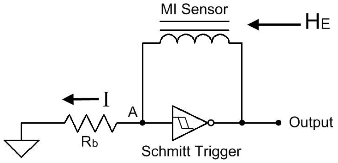
Figure 1Basic circuit showing the working principle of the magneto-inductive technology. The Schmitt trigger flips the direction of the current that causes the sensor to charge and discharge in both directions (from Leuzinger and Taylor, 2010).
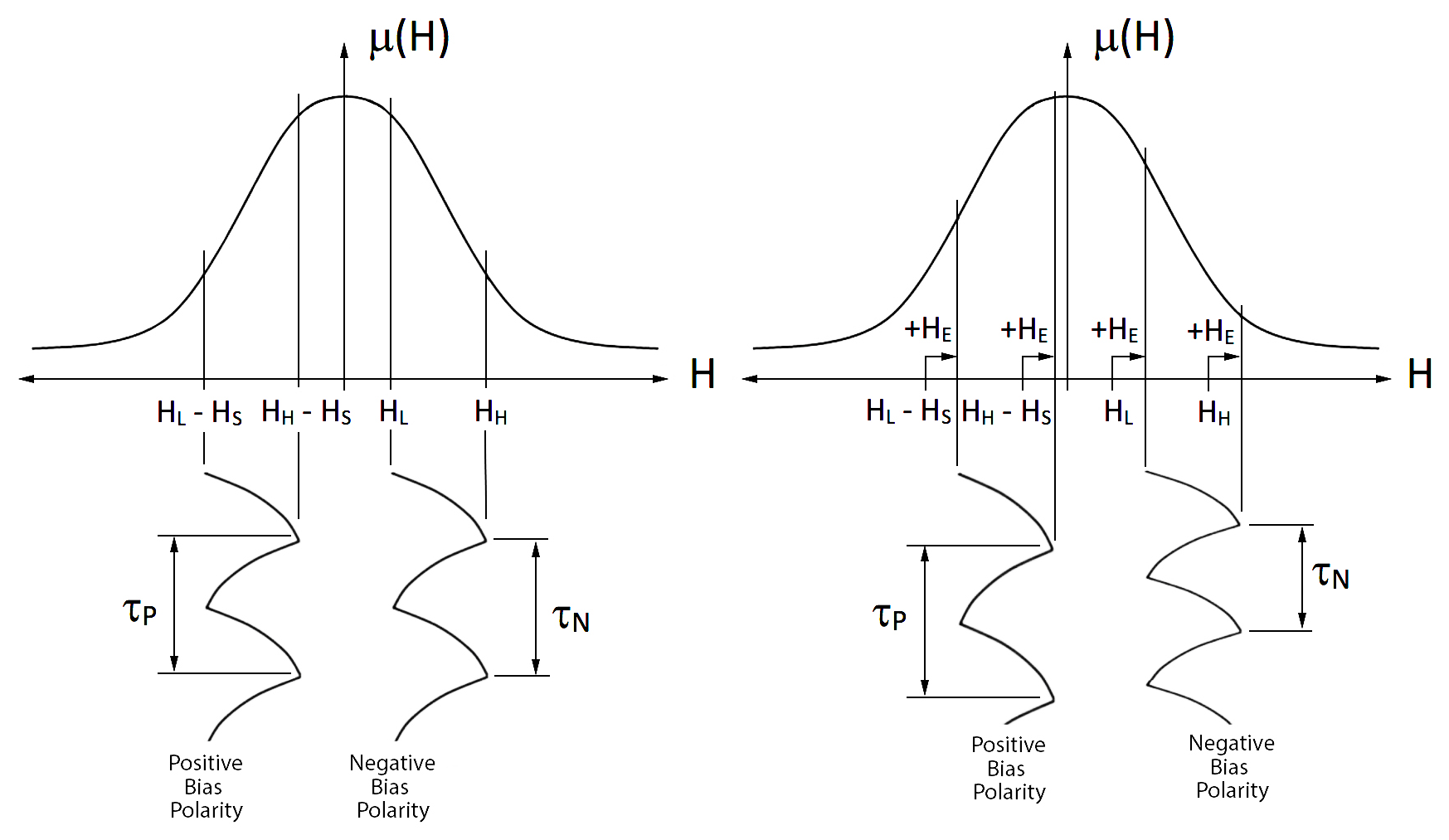
Figure 2Permeability curve of the core material of the sensors, showing the region of operation and difference in charge and discharge times in the absence (left) and presence (right) of an external magnetic field (from Leuzinger and Taylor, 2010).
By flipping the direction of the current, the circuit causes the inductor to go through consecutive charge and discharge cycles in both directions. The field sensed by the coil is a combination of the ambient field and the self-induced field due to the current flow. The selection of the current dictates the region in the permeability curve where the sensor works (Fig. 2).
In the absence of an external magnetic field, the charge and discharge times in both directions are the same. If an external field is present, the disturbance represented by it will cause the sensor to work in a different region of the permeability curve, causing a change in the charge and discharge times in each direction. Due to the particular shape of the permeability curve, the magnitude of this change is different for each direction and, by measuring the time difference between both cycles, the external field can be determined.
One of the advantages of the magneto-inductive technology is that the measurement principle is completely digital, with no power-consuming and radiation-sensitive components such as an analogue-to-digital converter (ADC) or amplifiers. This helps the sensor provide magnetic field measurements with very low power consumption and good tolerance to radiation.
This paper presents the results obtained for TID on nine different RM3100 sensors during two different test sessions completed between April and July 2019. The original aim of the tests was to study the survivability of the sensor to a TID of 300 krad(SI), in preparation for a potential landed mission to the Jovian moon Europa.
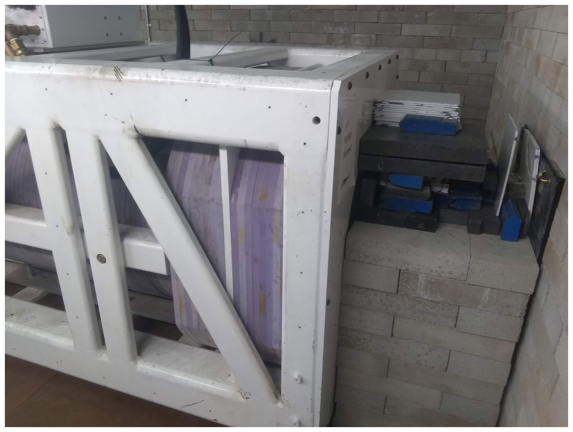
Figure 4Detail of the output end of the Varian M9 linear accelerator at the Department of Nuclear Engineering and Radiological Sciences at the University of Michigan. The exit of the beam is located at the right-hand side of the figure, and the magnetometer being irradiated is located behind the wall on the right.
Figure 5Magnetometers and dosimeters ready to be tested at the GSFC Radiation Effects Facility.
Figure 6Magnetic field magnitude measured during the radiation tests at the Department of Nuclear Engineering and Radiological Sciences at the University of Michigan.
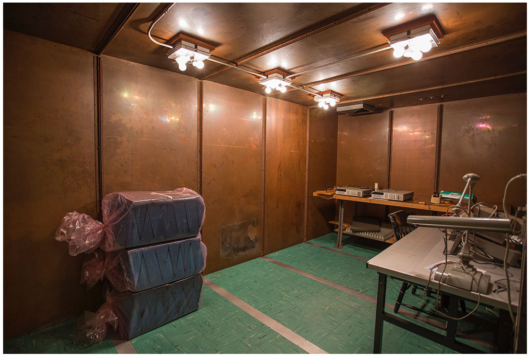
The tests presented here were performed in four different stages. The first and fourth stages involved the pre- and post-exposure characterization of the sensors being used in the study. For both stages, a zero-Gauss chamber that is located at the Climate and Space Research Building, at the University of Michigan was used (Fig. 3). Inside the zero-Gauss chamber, periodic and small variations in the field that might take place during the measurements are reduced to a value that is below the resolution of the instrument, as reported in Regoli et al. (2018).
The second stage involved the exposure to an X-ray beam of three of the sensors and it was carried out at the Department of Nuclear Engineering and Radiological Sciences at the University of Michigan. The radiation source used was a commercially available Varian M9 linear accelerator (Fig. 4). The output of the linear accelerator is an 9 MeV bremsstrahlung (X-ray) beam with nominal energy of 9 MeV. The maximum dose rate of the Varian M9 is of 3 krad(SI) min−1 at 1 m, but all the tests performed were run at 20 % of that capacity, 600 rad(SI) min−1 at 1 m. The sensors were placed at 25 cm from the source, and since the dose rate decreases according to a 1∕r2 factor, the radiation rate at the sensors during the tests was of 9.6 krad(SI) min−1.
The third stage involved the exposure to a gamma ray (X-rays originating within the nucleus) field of six of the sensors and it was carried out at the NASA Goddard Space Flight Center Radiation Effects Facility high-dose-rate total-ionizing dose irradiator (Fig. 5). The sensors were situated within a spectrum-modifying PbAl filter box, which preferentially reduces lower-energy photons. A standard assumption is that TID radiation is composed entirely of 1 MeV photons, but in reality that pure original radioactive decay spectrum is smeared downwards in energy as the photons interact with mass. As photon energy decreases from 1 MeV, the likelihood of interaction with matter increases, and this makes lower-energy photons more damaging than the desired, higher-energy, photons. Attenuation of the substantial lower-energy portion of the spectrum is the aim of the filter box.
Figure 7Magnitude of the magnetic field as measured by sensors 4 (a) and 5 (b) during the test campaign at the GSFC. The data shown between vertical lines correspond to 2 min intervals collected between exposures. The vertical lines mark the TID that the sensors went through before taking the measurements.

Figure 8Magnitude of the magnetic field as measured by sensors 8 (orange) and 9 (black) during the test campaign at the GSFC. Sensor 8 started failing after a TID of 150 krad(SI).

Figure 9Pre- and post-exposure (left and right panels, respectively) measurements of the magnetic field inside the zero-Gauss chamber at the University of Michigan for the three sensors used during the University of Michigan test campaign.
Figure 10Pre- and post-exposure (left and right panels, respectively) measurements of the magnetic field inside the zero-Gauss chamber at the University of Michigan for the six sensors used during the GSFC test campaign.
This section summarizes the test setup and the results obtained for each individual magnetometer. To make the information easier to follow, a subsection for each of the test campaigns is provided, with a detailed description of each particular test and for any special behavior of the sensors when applicable. In addition, each of the nine magnetometers is numbered according to the order in which they were exposed, and this numeration is maintained consistently throughout the paper.
Two different types of tests were performed in terms of whether the sensor was capturing data during exposure or not. The tests when the sensors were capturing data are referred to as active, while the other ones, when the sensors were unplugged from their power supply, are referred to as passive. For all the active tests, the magnetometer worked at a data rate of 40 Hz.
5.1 Test campaign 1: University of Michigan
Using the Varian M9 linear accelerator described in the previous section, the first sensor (sensor 1) was exposed while operating (active test) from 0 to 300 krad(SI) in steps of 50 krad(SI) and the output briefly analyzed after each set of exposures. During the test, the magnetometer survived without any apparent degradation of the signal until 300 krad(SI), so two extra steps of 100 krad(SI) each were used to bring the TID to 500 krad(SI).
Figure 6 shows the magnitude of the magnetic field measured by sensor 1 in nanoteslas during each of the exposure steps, all in a single plot. Each exposure is plotted with a different color. The first six exposures were 50 krad(SI) steps with a final dose of 300 krad(SI). The last two steps were of 100 krad(SI) each for a total final dose of 500 krad(SI). The plot only shows results up to 450 krad(SI) since the sensor started failing at around that level.
Two variabilities of interest are visible in the plot. The first one is a steady increase in the total field throughout the duration of the test that becomes particularly pronounced after the TID reaches approximately 225 krad(SI) and continues right until failure of the sensor at above 450 krad(SI). Additionally, for each exposure step, a small change in the field being measured and an increase in the noise is present. The source of this variability is the accelerator itself. At the beginning and end of each step, data were collected during a short period of a few seconds without exposure, while the accelerator was switched on and off.
The two other magnetometers exposed to the beam from the Varian M9 linear accelerator (sensors 2 and 3) were exposed while disconnected (passive test) in a single exposure from 0 to 300 krad(SI). With a rate of 9.6 krad(SI) min−1, the total exposure lasted just over 31 min. Once the exposure was finished, the sensors were removed from the testing facility and they were tested afterwards inside the zero-Gauss chamber for functioning, as well as performance degradation. The results for this post-exposure tests are presented at the end of this section.
5.2 Test campaign 2: Goddard Space Flight Center
A total of six individual sensors were irradiated using the TID irradiator located at the Goddard Space Flight Center (GSFC). The first two sensors (sensors 4 and 5) were tested passively but this time in steps of 25 krad(SI), collecting data after each exposure to test their survivability and performance degradation.
Figure 7 shows the results of these measurements for sensors 4 (top panel) and 5 (bottom panel). Each panel shows a series of 2 min measurements taken right after each 25 krad(SI) exposure step (marked by the vertical line at the right of each measurement). Since the lab environment where the measurements were taken was not controlled in terms of magnetic noise, the absolute values for each magnetometer and each step are irrelevant. However, what can be seen in both plots is the failure rate (seen in the plots as extremely high or low values of the measured field) of the sensors with increasing TID.
While sensor 4 shows no signs of failure whatsoever throughout the duration of the test, sensor 5 started failing right after reaching the 50 krad(SI) level. The rate of failure (measured as the ratio of invalid measurements to valid measurements) changes with time, although not monotonically as it would be expected, with two particularly faulty sets of measurements after reaching 150 krad(SI) and after reaching 200 krad(SI) with failure rates of 38 % and 54 %, respectively. However, even after these periods with high failure rate, after another exposure bringing the TID to 225 krad(SI), the failure rate went down to zero. This erratic behavior is probably due to damages in the application-specific integrated circuit (ASIC) that produce random upset events. Interestingly, even with some failure rates, the sensor survived up to the 300 krad(SI) exposure level and continued delivering relatively steady data.
In order to study the effect of dose rate, sensors 6 and 7 were tested passively. First, a single exposure between 0 and 250 krad(SI) at a low rate of 0.26 krad(SI) h−1 was completed. After this, a second exposure between 250 and 300 krad(SI) at a higher rate of 3.17 krad(SI) h−1 was completed. In this case, both sensors survived the total exposure and none of them showed signs of failure or signal degradation in the form of an appreciable change in the noise levels, measured as the standard deviation of the detected signal.
The last two sensors (sensors 8 and 9) were actively tested while being irradiated in a single step from 0 to 300 krad(SI). The results for both sensors are shown in Fig. 8. Shortly after reaching 150 krad(SI), sensor 8 (orange curve) started to fail, while sensor 9 continued working continuously until reaching 300 krad(SI). At around 180 krad(SI) some discontinuities are visible in the data returned by sensor 9. At this point, the test was temporarily suspended to check on the functioning of sensor 8. So the visible spikes are noisy data from the times when the test was stopped and re-started.
There is a clear change in slope that occurs at around 120 krad(SI) where both sensors start to show a steady increase in the measured magnitude of the field. This steady increase can be due to a real increase in the external field or due to the buildup of charges inside the semiconductors arising from the radiation exposure. Although no ground-truth values of the external field were available during the tests, the fact that a step is visible in the readings of sensor 9 between the moment when the test was briefly stopped and re-initiated seems to indicate that this slope is in fact produced by charge buildup.
5.3 Post-exposure evaluation
In order to evaluate the performance degradation of the sensors with time, all nine sensors exposed during the two campaigns reported in this paper were tested in the lab before and after the campaigns. Both sets of measurements were taken for each sensor for a total of 10 min. The measurements were performed inside the zero-Gauss chamber at the University of Michigan. The pre-exposure measurements were taken within 2 d of each exposure campaign, while the post-exposure measurements were taken approximately a month after the campaigns.
Figures 9 and 10 show the magnitude of the magnetic field measured during the pre- (left panels) and post-exposure (right panels) tests for each of the nine magnetometers studied. The title of each plot shows the standard deviation of the measured signal, which is a measure of the instrument noise.
The first thing to notice is that eight of the nine magnetometers continued to work without failure after the exposure was stopped, with only sensor 5 (data shown in bottom panel of Fig. 7) not showing any data (complete failure). The other sensor that showed some level of failure during the tests (sensor 8) went back to normal functioning. These two results mean that there are at least two different failure modes in the sensor. While the failure present during testing for sensor 8 might have been related to charge buildup (something also indicated by the fact that the sensor was able to run, changing the cycle count even while being irradiated), the failure in sensor 5 must have caused a permanent damage in the ASIC, possibly a charge-buildup-induced short circuit.
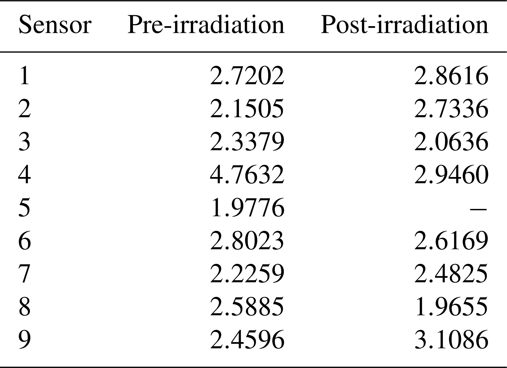
It is also interesting to look at the difference in standard deviation between the measurements taken prior to and after the exposure campaigns. No appreciable difference is present for any of the working magnetometers, meaning that no degradation in the performance occurred. The same behavior can be observed with the noise floors of the sensors before and after irradiation, given as the value of the power spectrum density at 1 Hz. These are presented in Table 1.
A total of nine individual RM3100 magnetometers were irradiated at different dose rates, all of them up to a TID of at least 300 krad(SI). Of the nine sensors tested, two showed some type of failure during the irradiation procedure, although one of them was able to continue working after changing the sampling frequency. This gives a success rate, just in terms of functionality (without considering performance), of 78 % to 89 %. There was no apparent correlation between failure rates and the nature of the irradiation in terms of active vs. passive irradiation or dose rate.
After the end of all the tests, the irradiated sensors were stored and later prepared for a post-irradiation test, similar to that performed at the beginning, during the characterization period. For this stage, the nine sensors were tested inside the zero-Gauss chamber for a period of 5 min. Eight of the nine sensors provided data and for those that continued working no degradation in performance was detected. This means that at least one magnetometer that presented errors during irradiation (sensor 8) completely recovered, while sensor 5 did not. While the tests presented in this paper do not allow us to specifically identify which part of the sensor failed, given that all the logic is carried out inside an application-specific integrated circuit (ASIC), it is expected that this is the component that is being affected during the exposure.
For a Europa lander mission, based on the Europa Science Definition Team (SDT) report (Europa Lander Science Definition Team, 2016, Fig. 6.5), the dose rate expected inside a 7.62 mm aluminum shielding is of approximately 7.7 krad(SI) d−1 or about 320 rad(SI) h−1. The sensors were exposed at a different range of dose rates going from 260 rad(SI) h−1 to over 3 krad(SI) h−1 at the GSFC facility, and up to 9.6 krad(SI) min−1 at the University of Michigan facility, thus mimicking and exceeding the conditions expected during a real mission, not only in terms of TID but also of dose rate.
All the tests performed during the reported campaigns were with the whole magnetometer, including not only the sensing coils but also the electronics. In reality, the coils can be separated from the electronics and, since the part that is really susceptible to radiation damage are the electronics, a small enclosure with extra shielding could easily be accommodated inside the planned vault in order to further shield the instrument. This is possible due to the very low mass (less than 3 g) and volume (about 6.4516 cm2) of the magnetometer. This would allow the sensing coils to be far from the magnetically noisy environment that is expected to be present inside the vault due to the presence of other instruments and spacecraft subsystems.
Increasing the shielding by 2.54 mm would bring the TID over the 20 d of the mission down to approximately 100 krad(SI) (200 krad(SI) using the design factor of 2), and by adding extra 2.54 mm the total TID would be approximately 75 krad(SI) (150 krad(SI) with the design factor of 2). Given that the sensor that failed at the lowest TID level (sensor 5) started failing at 150 krad(SI), this means that an extra shielding of 5 mm for the electronics would guarantee 100 % survivability without any failure for all the sensors used during the test campaigns.
All the data obtained during the different tests presented in this paper can be accessed through the University of Michigan's Deep Blue repository system under the DOI number https://doi.org/10.7302/hs4j-7064 (Regoli, 2020).
LHR took part in the design of the tests, participated in the irradiation campaigns, ran all the post-irradiation tests, and prepared the manuscript. MBM took part in the design of the tests. CR took part in the design of the tests, ran all the pre-irradiation tests, and participated in the irradiation campaigns. TAN contributed with his expertise in the radiation environment in the vicinity of Europa and provided calculations to estimate expected TID during a potential mission. CMA and SAP managed the linear accelerator at the University of Michigan. Martin Carts managed the irradiator at the Goddard Space Flight Center facility. All co-authors participated in the revision of the manuscript.
The authors declare that they have no conflict of interest.
Tom A. Nordheim acknowledges support from the Jet Propulsion Laboratory, California Institute of Technology, under a contract with NASA.
This work was supported by a NASA Instrument Concepts for Europa Exploration (80NSSC19K0608) and a NASA Heliophysics Technology and Instrument Development for Science (80NSSC18K1240). This work was also supported by the Consortium for Verification Technology under the Department of Energy National Nuclear Security Administration (DE-NA0002534) and the US Department of Homeland Security, Countering Weapons of Mass Destruction Office, Academic Research Initiative (2016-DN-077-ARI106).
This paper was edited by Olivier Witasse and reviewed by two anonymous referees.
Badhwar, G. D.: The Radiation Environment in Low-Earth Orbit, Radiat. Res., 148, S3–S10, https://doi.org/10.2307/3579710, 1997. a
Cooper, J. F., Johnson, R. E., Mauk, B. H., Garrett, H. B., and Gehrels, N.: Energetic Ion and Electron Irradiation of the Icy Galilean Satellites, Icarus, 149, 133–159, https://doi.org/10.1006/icar.2000.6498, 2001. a
Europa Lander Science Definition Team: Europa Lander Study, Tech. rep., NASA, Pasadena, CA, 2016. a, b, c
Hands, A. D. P., Ryden, K. A., Meredith, N. P., Glauert, S. A., and Horne, R. B.: Radiation Effects on Satellites During Extreme Space Weather Events, Space Weather, 16, 1216–1226, https://doi.org/10.1029/2018SW001913, 2018. a
Khurana, K. K., Kivelson, M. G., Hand, K. P., and Russell, C. T.: Electromagnetic Induction from Europa's Ocean and Deep Interior, in: Europa, University of Arizona Press, Tucson, Arizona, USA, 2009. a
Kovtyukh, A. S.: Ion Composition of the Earth's Radiation Belts in the Range from 100 keV to 100 MeV/nucleon: Fifty Years of Research, Space Sci. Rev., 214, 124, https://doi.org/10.1007/s11214-018-0560-z, 2018. a
Leuzinger, A. and Taylor, A.: Magneto-Inductive Technology Overview, Tech. rep., PNI Sensor Corporation, Santa Rosa, California, USA, 2010. a, b
Netzer, R., Avery, K., Kemp, W., Vera, A., Zufelt, B., and Alexander, D.: Total Ionizing Dose Effects on Commercial Electronics for Cube Sats in Low Earth Orbits, in: 2014 IEEE Radiation Effects Data Workshop (REDW), Boston, Massachusetts, USA, 1–7, https://doi.org/10.1109/REDW.2014.7004607, 2014. a
Paranicas, C., Carlson, R. W., and Johnson, R. E.: Electron bombardment of Europa, Geophys. Res. Lett., 28, 673–676, https://doi.org/10.1029/2000GL012320, 2001. a
Prinzie, J., Steyaert, M., and Leroux, P.: Radiation Effects in CMOS Technology, pp. 1–20, Springer International Publishing, Cham, https://doi.org/10.1007/978-3-319-78616-2_1, 2018. a
Regoli, L. H.: Sensor data for “Radiation tolerance of the PNI RM3100 magnetometer for a Europa lander mission”, https://doi.org/10.7302/hs4j-7064, last access: 22 December 2020. a
Regoli, L. H., Moldwin, M. B., Pellioni, M., Bronner, B., Hite, K., Sheinker, A., and Ponder, B. M.: Investigation of a low-cost magneto-inductive magnetometer for space science applications, Geosci. Instrum. Meth., 7, 129–142, https://doi.org/10.5194/gi-7-129-2018, 2018. a, b
Sajid, M., Chechenin, N., Torres, F. S., Hanif, M. N., Gulzari, U. A., Arslan, S., and Khan, E. U.: Analysis of Total Ionizing Dose effects for highly scaled CMOS devices in Low Earth Orbit, Nucl. Instrum. Meth. B, 428, 30–37, https://doi.org/10.1016/j.nimb.2018.05.014, 2018. a