the Creative Commons Attribution 4.0 License.
the Creative Commons Attribution 4.0 License.
 | 10 Jun 2021
Vibration error compensation algorithm in the development of laser interference absolute gravimeters
Yuntian Teng
Xiaomei Wang
Yanxiong Wu
Yang Zhang
Measurement error arising from vibration interference is recognized as the primary obstacle limiting the accuracy and stability of laser interference absolute gravimeters. The present work addresses this issue by proposing a global search optimization algorithm that determines the optimal absolute value of gravity based on the measured time–displacement coordinates of a falling body and the signal obtained from the passive vibration isolation system of the inertial reference corner cube in a laser interference absolute gravimeter. Results of numerical calculations conducted under vibration interference conditions with added white noise resulting in a signal-to-noise ratio of 40 dB demonstrate the following.
-
The accuracy and standard deviation of the gravimeter obtained using the proposed algorithm are −0.04 µGal ( m s−2) and 0.24 µGal, respectively, while those values obtained by the standard least-squares solution are 10.19 and 154.11 µGal, respectively.
-
The test results indicate that the average response of the reference value of acceleration due to gravity superimposed by a disturbance of 1.00 µGal is 1.01 µGal using the proposed algorithm and 0.87 µGal using the standard least-squares solution.
- Article
(1166 KB) - Full-text XML
- BibTeX
- EndNote


Laser interference absolute gravimeters are high-precision gravimetry instruments that are widely used in various fields such as metrology (Ouedraogo et al., 2007), solid geophysics (D'Agostino et al., 2008), seismic observation (Timofeev et al., 2018; Zhang, et al., 2019), and geodesy (Xing et al., 2017). These instruments measure the vertical position of a free-falling test body in a drop chamber under vacuum using a laser interferometer that generates an optical interference fringe each time the test body falls a distance equal to one-half of the wavelength of the laser light, and the timing of the fringes is determined from an atomic clock, which thereby provides highly precise time–displacement coordinates to determine the acceleration of the test body due to gravity.
However, vibrations caused by the servomotor-driven mechanism in laser interference gravimeters and environmental vibrations are coupled during the measurement process and introduce vibration error into the measurement result by affecting the inertial state of the reference corner cube (Wu et al., 2012). This vibration error has become the primary obstacle limiting the accuracy and stability of laser interference absolute gravimeters and affects absolute gravity measurement instruments based on the principle of atomic interference (Wu et al., 2019; Ménoret et al., 2018).
Numerous approaches have been developed for addressing the critical issue of vibration error. For example, the Micro-g LaCoste FG5 absolute gravimeter based on laser interferometry has obtained nearly ideal vibration error handling using a delicate design mechanism denoted as a superspring (Rinker, 1983; Hinderer et al., 2002). However, this solution suffers from a complicated structure and inflexibility for extending its application range. Other approaches developed for this purpose mainly include decreasing the self-system vibration of the instrument (Niebauer et al., 2011), vibration isolation technology (Nelson et al., 1991; Newell et al., 1997; Richman et al., 1998; Li et al., 2014), and vibration error compensation algorithms (Long et al., 2012; Wang et al., 2017). One of the simplest and most feasible technologies employs a passive vibration isolation system (PVIS) to suspend the reference corner cube (Zumberge et al., 1986). However, current practical applications of the PVIS remain far from meeting the requirements of instrument stability, accuracy, and precision under different observation conditions.
This issue is addressed in the present work by applying the PVIS in conjunction with a specifically developed vibration error compensation algorithm. To this end, we first analyze the PVIS of the reference corner cube to obtain the transfer function of the system as a vibration isolation device and a signal detection device and thereby establish a vibration interference error model. Then, the error model is employed to develop a new vibration error compensation algorithm (VECA) that conducts a global search based on a genetic algorithm (Wu et al., 2018) to determine the optimal absolute value of gravity based on the measured time–displacement coordinates of the falling body and the signal obtained from the PVIS of the reference corner cube in the laser interference absolute gravimeter. Finally, the accuracy, standard deviation and resolution of the gravimeter obtained using the proposed algorithm are evaluated by numerical calculations conducted under vibration interference conditions, and the results are compared with those obtained using the standard linear least-squares solution (LSS). The results demonstrate that the proposed algorithm provides a substantial anti-vibration capability and is worthy of application within absolute gravimeter designs based on laser interferometry.
2.1 System analysis of the PVIS
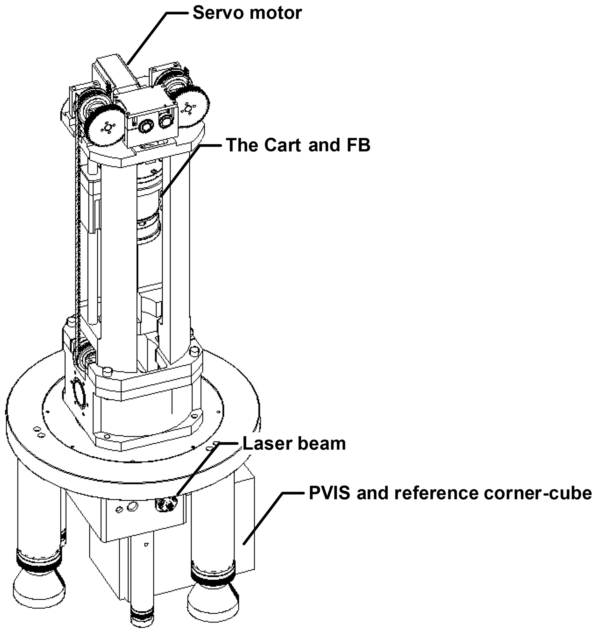
As illustrated in Fig. 1, the main component of a laser interference absolute gravimeter is a drop chamber under vacuum, inside which the test mass serving as a falling body (FB) is positioned within a cart mechanism that serves to raise, release, and catch the FB. There is no mechanical connection between the FB and the cart. The cart mechanism is driven by a servomotor installed on the outside of the drop chamber. After raising the FB to its initial position, the cart is accelerated downward by the servomotor at an acceleration rate slightly greater than that due to gravity until the FB is freely falling. Then, the motion of the cart is matched with the free-falling motion of the FB, and the time–displacement coordinates of the FB relative to the reference corner cube are measured. However, random vibrations are introduced during the measurement process, which are caused by the servomotor in the instrument and human activities within the measurement environment. Accordingly, the vibration error is coupled with the calculation results for the absolute value of the acceleration due to gravity.
The PVIS used to reduce the influence of vibration interference on the inertial state of the reference corner cube is illustrated schematically in Fig. 2, in which the reference corner cube and the mass block of the PVIS assembly of mass M are connected with the ground by a spring of stiffness K and a damping mechanism with a damping factor σ. Damping is produced by a mechanism employing a coil and magnetic steel structure that is commonly used in seismometers, where the value of σ is adjusted by varying the coil current. The displacement x(t) of the assembly relative to the ground is directly output by a precisely designed differential capacitance sensor and its corresponding circuitry. In addition, the absolute displacement of the ground is defined as y(t), and the absolute displacement of the assembly with respect to the earth centre of mass is defined as z(t). Finally, we note that the PVIS applies no closed-loop feedback at any point. Here, we found in actual experiments that the error arising from the feedback control system, particularly the overshoot, derived from another source in the measurements.
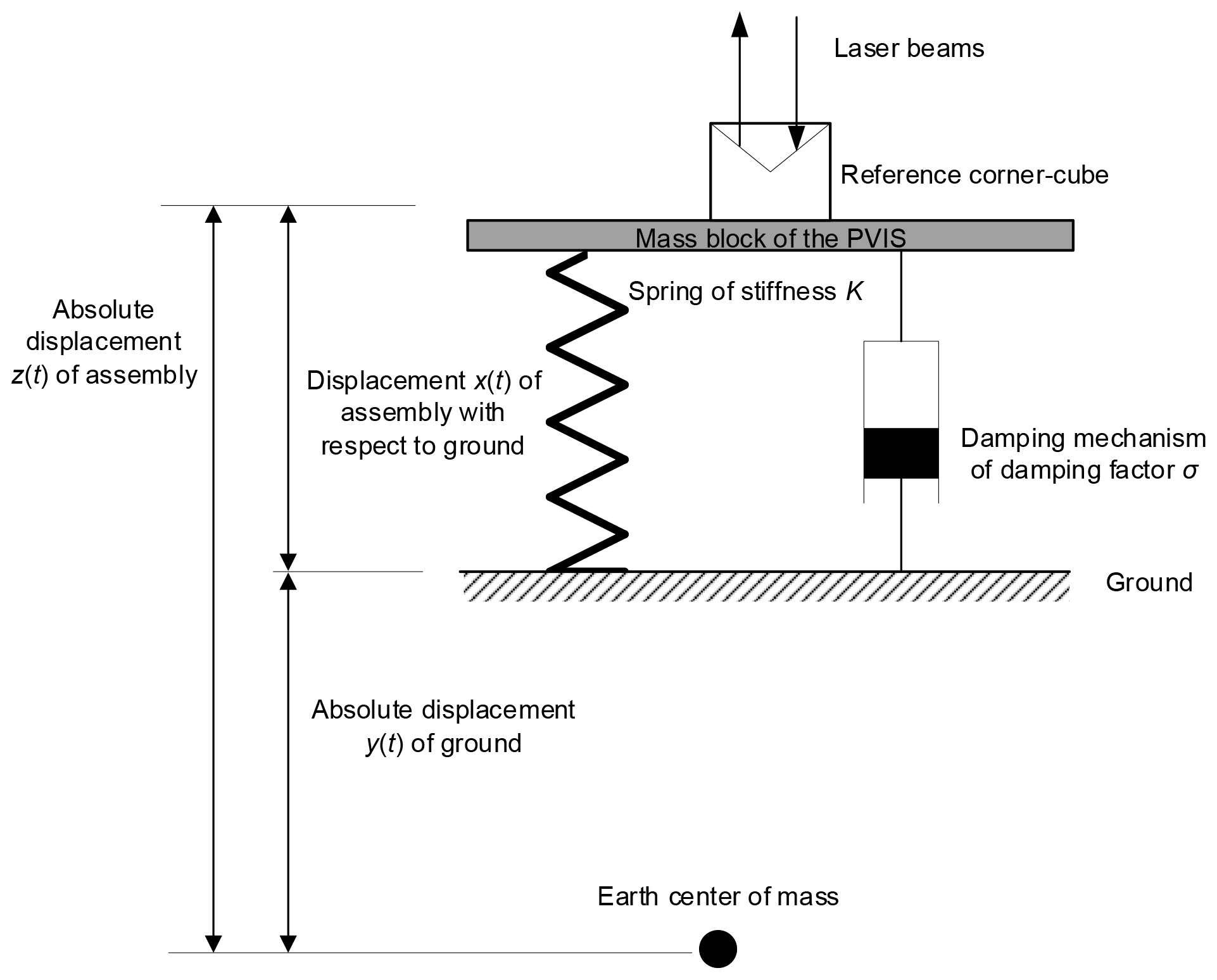
For conducting system analysis of the PVIS, we first note from Fig. 2 that and arbitrarily define the positive direction as vertically upward from the centre of mass of the earth. Accordingly, the dynamic equation of motion of the mass block of the PVIS and reference corner-cube assembly is given as follows (Thomson and Dahleh, 1972):
and its Laplace transform is
The transfer function of the vibration isolation effect of the PVIS can be given as follows:
where and the squared intrinsic frequency . The transfer function of the detection effect of the PVIS can be given as follows:
Applying Eq. (5) in conjunction with Eq. (3) yields the following:
The attenuation amplitude versus frequency and phase–frequency characteristic curves of Φ1(s) and Φ2(s) are plotted in Fig. 2 for K=50 N mm−1, σ=60, and M=5 kg. It can be seen from the amplitude–frequency curve that the vibration isolation operation of the PVIS (i.e., Φ1(s)) attenuates signals in y(t) above the intrinsic frequency. The vibration isolation effect will become increasingly obvious as the frequency of the signals increases above the intrinsic frequency, but these high-frequency signals after attenuation will still be coupled in the measurement system of the absolute gravimeter, and signals below the intrinsic frequency will be directly coupled into the measurement system without attenuation. In terms of the signal detection operation of the PVIS (i.e., Φ2(s)), signals above the intrinsic frequency will be detected without any attenuation, but signals below the intrinsic frequency are attenuated.
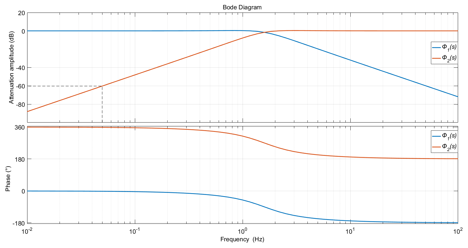
Figure 3Amplitude–frequency and phase–frequency characteristic curves of the vibration isolation operation of the PVIS and its signal detection operation. Here, the phase information is not unwrapped.
Because of the height restrictions of the drop chamber, the free-falling distance of the FB is controlled within 20 cm, and the free-falling period is about 0.2 s, which can be regarded as the maximum period of the vibration interference signal with a corresponding frequency of 5 Hz. If we consider that signals with amplitude attenuations greater than −60 dB are effectively attenuated, signals from approximately 0.05 Hz to the intrinsic frequency of the system will still exist in the output signal of the PVIS, although they will be attenuated. Meanwhile, signals below 0.05 Hz can be considered to vary linearly with respect to time during the measurement period of 0.2 s. Additionally, it can be seen from the phase–frequency curves in Fig. 3 that the phases of Φ1(s) and Φ2(s) maintain a consistent relationship. Therefore, the PVIS can be applied as both a vibration isolation device for the reference corner cube and a detection sensor of the vibration signal of the reference corner cube simultaneously. Most of the useful signals related to the disturbance error of the absolute gravity measurement in Z(s) can be recovered by the synchronously output vibration signal X(s) in conjunction with Eqs. (4) and (6) owing to the precise values of β and ω0 obtained from the PVIS hardware system.
2.2 Mathematical model of the vibration error
In absolute gravimetry, the general method for treating a vertical gradient of the earth's surface is that the vertical gravity gradient of the measurement point is first assumed to be 0, and then the absolute acceleration of the effective height of the instrument (Zumberge, 1981; Niebauer, 1989; Timmen, 2003) is obtained using the absolute gravity measurement instrument. In addition, at least two sets of relative gravimeters are used to measure the vertical gravity gradient of the measurement point either before or after conducting the absolute gravity measurement. Finally, the absolute gravity measurement value of the effective height position is calculated relative to the ground or other height position based on the obtained vertical gradient. Because this paper mainly analyses the impact of vibration errors on gravity measurement results, we adopt the following simplified model for the factors affecting the measured displacement S(ti) of the FB as a function of time ti, where indexes the time coordinates established according to the rubidium atomic frequency standard:
Here, S0 and V0 are the initial displacement and velocity of the FB, g0 is the absolute value of gravity to be determined from the measurement point, d(ti) is the vibrational interference coupled to the measurement system, and e(ti) is additive white noise conforming to a normal distribution with a mean of 0 and a variance of 1. Here, d(ti) is the signal of interest that must be uncoupled from the measurement. For this purpose, we express the signal x(t) output from the PVIS as
where Ak, ωk, and φk are the amplitude, angular frequency, and initial phase of the kth harmonic signal, respectively. In addition, the second term on the right is the trend component with pj as the coefficient, where is , , and , while .
Extracting d(ti) from x(ti) requires that we consider the following two important aspects.
-
The voltage signal x(ti) derived from the PVIS has not been converted into a displacement via sensitivity calibration. However, the calibration error is on the order of 10−7 m generally, and the error in the displacement measurement of a microgravity absolute gravimeter must be less than 10−11 m at least (Christian, 2008). Accordingly, the sensitivity calibration error is much greater than the allowable error range of a microgravity absolute gravimeter.
-
As described in Sect. 2.1, the vibration signal x(ti) is not the absolute displacement of the reference corner cube z(t), but it is rather the result of the system transfer function, as described in Eq. (6), with which the low-frequency signals are subject to attenuation.
These issues are addressed to extract d(ti) from x(ti) by introducing comprehensive coefficients qak, qφk, and qpj influencing Ak, ωk, and pj to obtain the following (Akaike, 1980):
This equation can be rewritten as
where , , and the correction coefficients for the harmonic components are R1k=qakcos (qφk) and ). Next, we apply Eqs. (10) to (7) as follows:
where , , and
In this case, the term Q2 in Eq. (13) includes not only the quadratic term arising from acceleration due to gravity but also the quadratic term in the vibration interference. Therefore, obtaining accurate measurement values for g0 requires that qp2p2 be accounted for as follows:
2.3 Analysis of the vibration error compensation
Comparing Eqs. (11) and (13) indicates that, if we can obtain the exact values of S0, V0, and g from Eq. (13) by some algorithm like a global optimization algorithm, the theoretical parabolic equation can be obtained as
and the residual D0(ti) can be expressed as
In contrast, if relationship (Eq. 17) is satisfied, the values of S0, V0, and g can be obtained without any vibration errors. In addition, the satisfaction of Eq. (17) can be considered as a correlation coefficient of D0(ti) and d(ti) obtaining a maximum value after de-averaging as follows:
3.1 Algorithm design
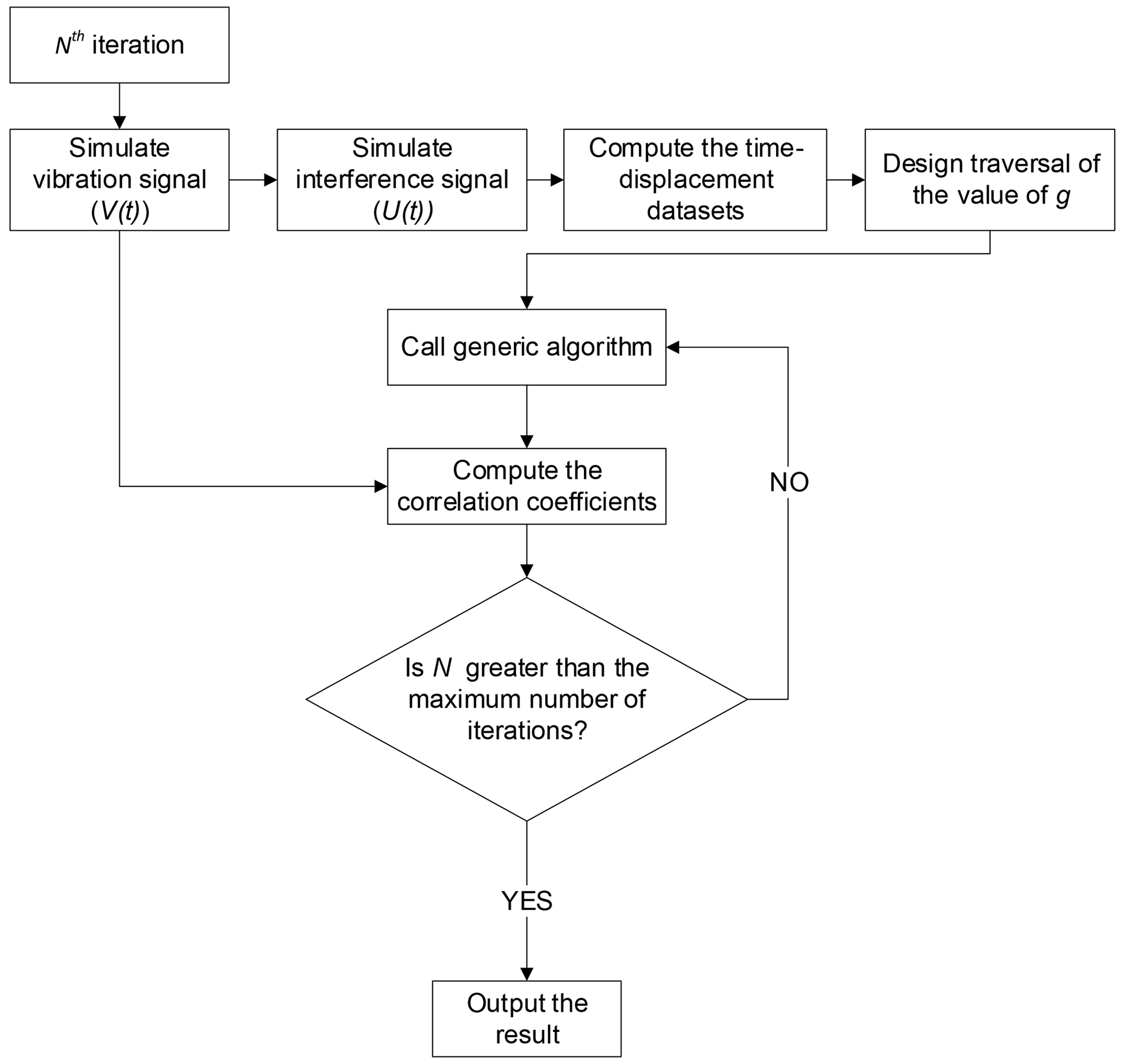
Of course, the proposed VECA can be solved using many other techniques, such as the gradient descent algorithm, random walk, and machine learning. However, evaluating an array of solution techniques would involve a tremendous amount of comparative analysis, which is prohibitive here due to space constraints. Therefore, the present work exclusively applies a genetic algorithm for solving the VECA and leaves an evaluation of other solution methods for future research. Genetic algorithms mimic Darwinian natural selection, where individuals are selected for subsequent mutation and breeding based upon their perceived level of fitness. The global search ability of genetic algorithms makes these algorithms ideally suited for obtaining solutions to the VECA. The objective function of the genetic algorithm is designed to maximize the correlation coefficients of the residual according to Eq. (17) and the signal from the PVIS by adjusting the values of the variables V0 and g. Accordingly, 80 values of both V0 and g are employed as members of the populations used by the genetic algorithm. The computational flow of the VECA for the ith iteration is illustrated in Fig. 4. The relevant parameters employed in the simulation process are set as follows.
-
Interference fringe signal simulation: the fringe signal U(ti) can be simulated according to the mathematical form of a fringe signal given by Murata (1978) after removing the DC component and linear drift as follows:
Here, U0 is the amplitude of the simulated fringe signal, set as U0=1 representative of a normalized signal, λ is the laser wavelength, set as 632.990439 nm, and S(ti) is the displacement of the FB defined by Eq. (7), where ti is the time of the ith sampling point obtained under an equal sample spacing at a sampling frequency of 100 MHz. Therefore, the sampling interval is s.
In addition, the absolute value of the acceleration due to gravity g0 is assumed to be 980 110 343.0 µGal in the simulation of the VECA. This term is used to generate the fringe signal required by the simulation of the VECA and is also used as a reference value to determine the accuracy of the results of the VECA and LSS calculations.
The anti-interference ability of the VECA is verified by replacing d(ti) in Eq. (7) with the two following vibration interference models in turn:
where m s−2, m s−1, and m. The frequency range considered was based on the effective frequency range for actual signal detection in the PVIS and the characteristic frequency range of natural system vibrations generated during instrument operation. From this range, 15 values of fk are randomly selected for each calculation, and the corresponding values of Ak are selected randomly as well under the constraint that the amplitude of the interference vibration signal after component superposition is m. The signal-to-noise ratio of d(ti) after superimposing e(ti) is 40 dB.
-
Time–displacement coordinates: the time–displacement coordinates are computed by the instantaneous phase of the fringe signal U(t) based on the Hilbert transform with phase unwrapping (Svitlov and Araya, 2014; Zumberge et al., 2004):
-
Initialize the ergodic range of g: first, an initial value of Q2 is obtained by LSS with S(t) defined by Eq. (22). It is known that the vibration error range introduced by qp2p2 will not exceed ±1000 µGal under the action of the PVIS in actual measurements (Wu., et al., 2012). Therefore, we ensure the rationality of the calculation results by setting the ergodic range of g as Q2±5000.
-
Set the parameters of the genetic algorithm: the maximum number of iterations is set as 150, the number of variables is 2, the number of individuals is 80, the number of binary coding digits of the variable is 50, and the generation gap is 0.9.
-
Design the objective function: the objective function is based on the correlation coefficients between D0(ti) and d(ti) given by Eq. (18), which is employed to complete the reinsertion, population restoration, and fitness allocation of the genetic algorithm.
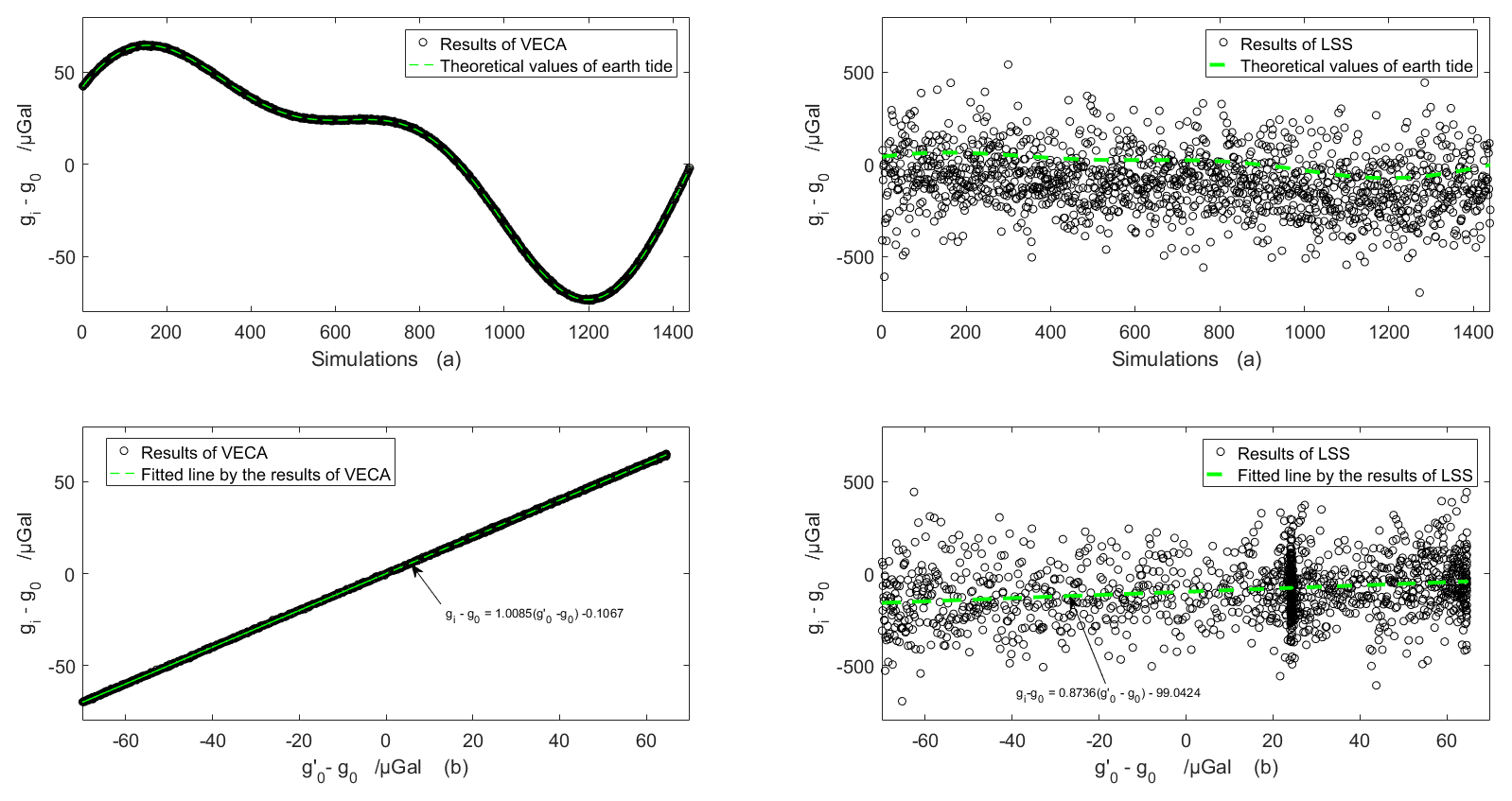
Figure 6Values of gi−g0 obtained for each minute by the VECA and LSS under the effect of the earth tide in Beijing on 1 May 2020 (a) and a plot of the gi−g0 values in (a) versus the values along with linear fitting to the results (b).
3.2 Accuracy and standard deviation of the VECA results
The accuracy of the VECA is calculated as
where gi is the ith measurement result, and n is the total number of measurements. The standard deviation of the VECA is calculated as
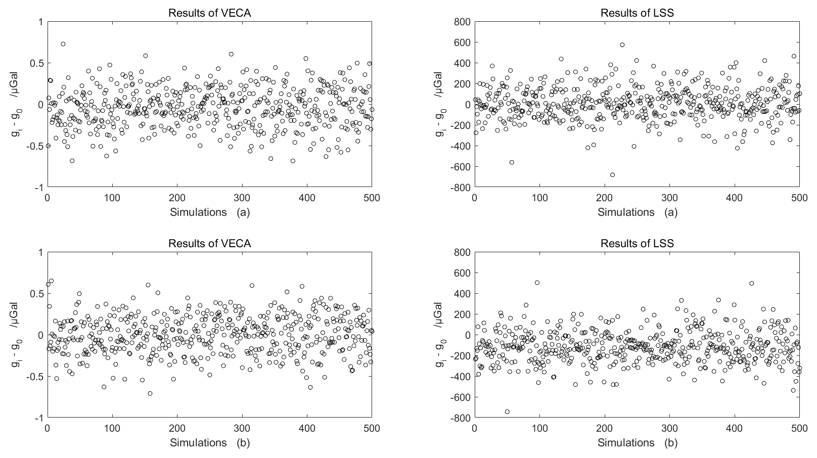
The vibration error suppression effect of the proposed VECA is illustrated for different types of vibration errors based on vibration interference signals (Eqs. 20 and 21), and the VECA and LSS are applied to each vibration signal 500 times. The values of gi−g0 obtained for each simulation by the VECA and LSS are presented in Fig. 5a and b for the interference signals given by Eqs. (20) and (21), respectively. We note that the VECA results are distributed in the range of ±0.8 µGal, the accuracy is −0.04 µGal, and the standard deviation is 0.24 µGal. The results of the LSS lie in the range of ±500 µGal, the accuracy is 10.19 µGal, and the precision is 154.11 µGal. Obviously, the proposed VECA improves the accuracy and precision of the measurement results under the condition of vibration interference much better than the LSS.
3.3 Resolution testing
The resolution of the algorithm was tested by first calculating the theoretical values of the earth tide Δgi at each minute in Beijing on 1 May 2020 (Munk and Cartwright, 1966). Then, Δgi is added to g0 as
to approximate the effect of Δgi on the absolute value of acceleration due to gravity in the regional gravity field at the same measurement period. The values of gi−g0 obtained at each minute by the VECA and LSS are presented in Fig. 6a for the interference signals defined in Eq. (21). The resolution of the test results is shown in Fig. 6b based on a plotting of the results of gi−g0 in Fig. 5a along the ordinate axis and a plotting of along the abscissa axis and then applying linear regression analysis to the results to obtain the slopes and intercepts of the fitted lines. The system deviation of VECA is −0.1067 µGal, and the average response of the reference value of acceleration due to gravity superimposed by a disturbance of 1 µGal is 1.0085 µGal. In contrast, the system deviation of LSS is −99.0424 µGal, and the average response of the reference value of acceleration due to gravity is 0.8736 µGal, which therefore fails to reflect changes in the acceleration due to gravity under the influence of the earth tide. Accordingly, we can conclude that the proposed VECA significantly improves the resolution of the measurement results relative to the LSS.
Using the PVIS to suspend the reference corner cube in a laser interference absolute gravimeter is a simple and feasible technology for reducing random vibration error in gravimetry measurements. A system analysis of the PVIS demonstrated the feasibility of applying the PVIS for both vibration isolation and signal detection simultaneously to improve the measurement accuracy of the absolute gravimeter. Next, a reference corner-cube vibration interference error model was developed and applied to construct the newly proposed VECA for improving the accuracy, precision, and resolution of the measured value of gravity using a genetic algorithm. The results of numerical calculations conducted under vibration interference conditions with added white noise resulting in a signal to noise ratio of 40 dB demonstrated the following.
-
The accuracy and standard deviation of the gravimeter obtained using the proposed algorithm are −0.04 and 0.24 µGal, respectively, while those values obtained by the standard LSS are 10.19 and 154.11 µGal, respectively.
-
The resolution of the test results shows that the average response of the reference value of acceleration due to gravity superimposed by a disturbance of 1 µGal is 1.01 µGal using the proposed algorithm and 0.87 µGal using the standard least-squares solution.
These results verify that making full use of the output signal of the PVIS can effectively improve the performance of the absolute gravimeter via the application of anti-vibration using the VECA. The VECA has a practical significance in decreasing requirements for vibration isolation hardware and thus improving the adaptability of the measurement environment in the development of laser interference absolute gravimeters.
The code used in this paper are availability from corresponding author upon reasonable request. All the data used were simulated and the method of the simulation has been described in the Sect. 3.1 and 3.3.
In this paper, QW and YT designed the method and developed the code. XW designed the method of the simulation. YW and YZ prepared the paper with contributions from all co-authors; they also completed the revised version considering reviewers' suggestion.
The authors declare that they have no conflict of interest.
We would like to thank the members of the project committee for their help, and we also acknowledge the anonymous referees and editors for their help, constructive remarks, and suggestions.
This research has been supported by the Special Fund of the Institute of Geophysics, China Earthquake Administration (grant no. DQJB19B23).
This paper was edited by Jean Dumoulin and reviewed by two anonymous referees.
Akaike, H.: Seasonal adjustment by a Bayesian modelling, J. Time Ser. Anal., 1, 1–13, https://doi.org/10.1111/j.1467-9892.1980.tb00296.x, 1980.
Christian, R.: Ultra-high Precision, Absolute, Earth Gravity Measurements, PhD thesis, Institute of Optics, Information and Photonics University Erlangen-Nuremberg, 2008.
D'Agostino, G., Desogus, S., Germak, A., Origlia, C., Quagliotti, D., Berrino, G., Corrado, G., d'Errico V., and Ricciardi, G.: The new IMGC-02 transportable absolute gravimeter: measurement apparatus and applications in geophysics and volcanology, Ann. Geophys., 51, 39–49, https://doi.org/10.4401/ag-3038, 2008.
Hinderer, J., Amalvict, M., Crossley, D., Leveque, J. J., Rivera, L., and Luck, B.: Tides, earthquakes and ground noise as seen by the absolute gravimeter FG5 and its superspring; comparison with a superconducting gravimeter and a broadband seismometer, Metrologia, 39, 495–501, https://doi.org/10.1088/0026-1394/39/5/11, 2002.
Li, G., Hu, H., Wu, K., Wang, G., and Wang, L. J.: Ultra-low frequency vertical vibration isolator based on LaCoste spring linkage, Rev. Sci. Instrum., 85, 104502, https://doi.org/10.1063/1.4897488, 2014.
Long, J. F., Huang, D. L., Teng, Y. T., Wu, Q., and Guo, X.: Study on vibration scribing algorithm for an absolute gravitational measurement, Acta Seismologica Sinica, 34, 865–872, https://doi.org/10.3969/j.issn.0253-3782.2012.06.013, 2012.
Ménoret, V., Vermeulen, P., Le Moigne, N., Bonvalot, S., Bouyer, P., Landragin, A., and Desruelle, B.: Gravity measurements below 10−9 g with a transportable absolute quantum gravimeter, Sci. Rep.-UK, 8, 12300, https://doi.org/10.1038/s41598-018-30608-1, 2018.
Munk, W. H. and Cartwright, D. E.: Tidal Spectroscopy and Prediction, Philos. T. Roy. Soc. A, 259, 533–581, https://sci-hub.ee/10.2307/73232 (last access: 7 June 2021), 1966.
Murata, I.: Transportable apparatus for absolute measurements of gravity, B. Earthq. Res. I. Toykyo, 53, 49–130, 1978.
Nelson, P. G.: An active vibration isolation system for inertial reference and precision measurement, Rev. Sci. Instrum., 62, 2069–2075, https://doi.org/10.1063/1.1142368, 1991.
Newell, D. B., Richman, S. J., Nelson, P. G., Stebbins, R. T., Bender, P. L., Faller, J. E., and Mason, J.: An ultra-low-noise, low-frequency, six degrees of freedom active vibration isolator, Rev. Sci. Instrum., 68, 3211–3218, https://doi.org/10.1063/1.1148269, 1997.
Niebauer, T. M.: Effective measurement height of Free-Fall absolute gravimeters, Merologia, 26, 115–118, https://doi.org/10.1088/0026-1394/26/2/005, 1989.
Niebauer, T. M., Billson, R., Ellis, B., Mason, B., Westrum, D. V., and Klopping, F.: Simultaneous gravity and gradient measurements from a recoil-compensated absolute gravimeter, Metrologia, 48, 154–163, https://doi.org/10.1088/0026-1394/48/3/009, 2011.
Ouedraogo, K., Topsu, S., Chassagne, L., Juncar, P., Nasser, J., and Alayli, Y.: Absolute method for an optical measurement of the earth gravitational axis: application to Watt Balance, Proc. SPIE, 6585, 65852G, https://doi.org/10.1117/12.722737, 2007.
Richman, S. J., Giaime, J. A., Newell, D. B., Stebbins, R. T., Bender, P. L., and Faller, J. E.: Multistage active vibration isolation system, Rev. Sci. Instrum., 69, 2531–2538, https://doi.org/10.1063/1.1148954, 1998.
Rinker, R. L.: Low-frequency vibration isolator, PhD thesis, University of Colorado, Ann Arbor, MI, 1983.
Svitlov, S. and Araya A.: Homodyne interferometry with quadrature fringe detection for absolute gravimeter, Appl. Optics, 53, 3548–3555, https://doi.org/10.1364/AO.53.003548, 2014.
Thomson, W. T. and Dahleh, M. D.: Theory of vibration with applications, Prentice Hall, Inc., Englewood Cliffs, NJ, 63–71, 1972.
Timmen, L.: Precise definition of the effective measurement height of Free-Fall absolute gravimeters, Metrologia, 40, 62–65, https://doi.org/10.1088/0026-1394/40/2/310, 2003.
Timofeev, V. Y., Kalish, E. N., and Stus, Y. F.: Gravity and Displacement Variations in the Areas of Strong Earthquakes in the East of Russia Izvestiya, Phys. Solid Earth, 54, 430–443, https://doi.org/10.1134/S1069351318030084, 2018.
Wang, G., Hu, H., Wu, K., and Wang, L. J.: Correction of vibration for classical free-fall gravimeters with correlation-analysis, Meas. Sci. Technol., 28, 035001, https://doi.org/10.1088/1361-6501/aa54f7, 2017.
Wu, Q., Hao, X. G., Teng, Y. T., and Guo, T. G.: Influence mode analysis of Self Vibration on absolute gravimeter, Geomatics and Information Science of Wuhan University, 37, 980–983, https://doi.org/10.1007/s11783-011-0280-z, 2012.
Wu, Q., Teng, Y. T., Zhang, B., and Xing, L. L.: Application of genetic algorithm to improving measurement accuracy of laser interference absolute gravimeter, Instrumentation, Mesure, Metrologie, 17, 467–477, https://doi.org/10.3166/i2m.17.467-477, 2018.
Wu, X., Pagel, Z., Pagel, Z., Malek, B. S., Nguyen, T. H., Zi, F., Scheirer, D. S., and Müller, H.: Gravity surveys using a mobile atom interferometer, Sci. Adv., 5, eaax0800, https://doi.org/10.1126/sciadv.aax0800, 2019.
Xing, L. L., Wang, L. H., and Hu, M. Z.: Determination of mantle upwelling rate beneath Taiyuan basin by using absolute gravity, GPS, J. Appl. Geophys., 138, 179–184, https://doi.org/10.1016/j.jappgeo.2017.01.026, 2017.
Zhang, Y., Chen, S., Xing, L. L., Liu, M., and He, Z. T.: Gravity changes before and after the 2008 Mw 7.9 Wenchan Earthquake at Pixian absolute gravity station in more than a decade, Pure Appl. Geophys., 177, 121–133, https://doi.org/10.1007/s00024-019-02356-4, 2019.
Zumberge, M. A.: A portable apparatus for absolute measurements of the Earth's gravity, PhD thesis, University of Colorado, Ann Arbor, MI, 1981.
Zumberge, M. A., Sasagawa, G., and Kappus, M.: Absolute gravity measurements in California, J. Geophys. Res., 91, 9135–9144, https://doi.org/10.1029/JB091iB09p09135, 1986.
Zumberge, M. A., Berger, J., Dzieciuch, M. A., and Park, R. L.: Resolving quadrature fringes in real time, Appl. Optics, 43, 771–775, https://doi.org/10.1364/AO.43.000771, 2004.