the Creative Commons Attribution 4.0 License.
the Creative Commons Attribution 4.0 License.
 | 04 Sep 2023
Research on online data transmission technology in a marine controlled-source electromagnetic transmitter
Chentao Wang
Ming Deng
Nini Duan
Xiaoxi Ma
Meng Wang
This paper proposes a method for acquiring complete status information and data from the marine controlled-source electromagnetic (MCSEM) transmitter during offshore experiments. The subordinate machine system is constructed on the STM32 platform and incorporates a real-time operating system. It utilizes the internet of things (IoT) concept to interconnect various modules within the transmitter, enabling intelligent control and management. At the same time, data are uploaded to the control room on the deck through photoelectric composite cables, and the host computer's software, designed with Python language, will process and store all the data. This allows workers on the deck to control the subordinate computer and obtain high-precision, complete data in real time. The joint tests between the subordinate and host computers have demonstrated the stability and reliability of the online transmitter system, which provides significant convenience for offshore exploration.
- Article
(2249 KB) - Full-text XML
- BibTeX
- EndNote


The marine controlled-source electromagnetic (MCSEM) method plays a crucial role in exploring sea oil and gas resources (Constable, 2006, 2010). During marine exploration, the research vessel utilizes the photoelectric composite deep-tow cable to tow the electromagnetic transmitter near the seafloor. The electromagnetic receiver then acquires the induction field source signal generated by the underground geological anomaly (Wang et al., 2013). After the instruments are recovered, the data collected from the receivers and transmitters are integrated, processed, and inverted to obtain the apparent resistivity of the seabed in the detected sea area (Connell and Key, 2013). This effectively identifies hydrocarbons and provides the basis for the exploitation of oil and gas resources (Li and Constable, 2010; Wang et al., 2019; Constable et al., 2016).
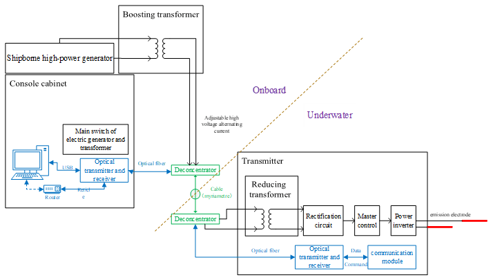
The research and development of MCSEM in China began in 2006, supported by the National High-tech Research and Development (R&D) Program (863 Program) and other national funds. A series of MCSEM instruments have been developed, including a mixed-field-source electromagnetic receiver, a towed receiver (Chen et al., 2013), a towed transmitter system (Wang et al., 2017a), and a deployed transmitter (Wang et al., 2017b). In terms of software, many teams have developed data-processing software (Pethick, 2016; Liu et al., 2018; Li et al., 2022), but these data-processing activities take place after the hardware is reclaimed. Additionally, other teams have developed state-monitoring software; nonetheless, these methods depend on locally deployed data, with merely a small fraction being uploaded to the deck for monitoring purposes (Wang et al., 2013; Xu et al., 2017; Zhao et al., 2021). The comprehensive data set for analysis typically becomes accessible only once the instrument is retrieved (Duan et al., 2018; Wang et al., 2022; Chen et al., 2020). This data acquisition method does not ensure the safety and promptness of the data. To minimize the risk of data loss and achieve real-time data transmission from the transmitter to the deck side, an online real-time data transmission system has been developed. Figure 1 depicts the relationship between the online transmission system and the entire system.
The main task of the lower computer part in the system is to store the data into the storage media as a file, according to a certain format, and provide an intermodule communication channel. Once the data from different modules are consolidated, they are transmitted via ethernet for uploading.
The upper computer is responsible for receiving data from the lower computer, storing it on the upper computer, and providing users with a user-friendly interface to control the lower computer.
2.1 Overall framework
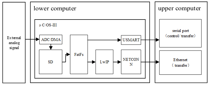
The main control unit in the lower computer is the STM32F407ZGT6 produced by STMicroelectronics. Using this unit, we deploy the data acquisition module, data storage module, serial communication module, ethernet communication module, and real-time operating system. In the system, data management is facilitated by the FatFs system, and we have reserved a USMART serial port function identification, and a NETCONN ethernet interface. The coordination of each module is illustrated in Fig. 2. The online transmission system we designed consists of two transmission channels. The serial port transmission channel is mainly responsible for transmitting control commands, while the ethernet transmission channel is mainly responsible for transmitting a large volume of data. These two channels do not interfere with each other. This consideration is based on the requirements for data file integrity and accuracy, as well as the limitations of the lower hardware.
In terms of hardware, in order to withstand strong electromagnetic interference in the transmitter, our equipment has undergone corresponding electromagnetic compatibility (EMC) verification, including, but not limited to, a fast pulse group, electromagnetic radiation and interference resistance, and electrostatic and insulation testing. Our optoelectronic composite cable has a power transmission function, which can continuously supply power underwater. Underwater power conversion adopts the combination of a transformer, charger, and battery, so there is no need to be overly concerned about power. However, our design for the underwater end still focuses on the low power consumption.
2.1.1 Task management based on µC/OS-III
We utilize µC/OS-III as the system to manage complex tasks on the lower computer. It is a preemptive, multi-tasking, and real-time operating system based on priority, which can significantly optimize the program structure, increase the readability, and improve portability. Each functional module is regarded as a subtask for the operating system to schedule. These modules are independent of each other and provide corresponding application programming interfaces (APIs), making it convenient to transplant and greatly optimizing the ethernet data transmission and command interaction.
2.1.2 File management based on FatFs
FatFs is a general file management module that is independent of the input/output (I/O) layer of the disk, making it a hardware architecture agnostic system. This allows the system to implement the related functions of a file allocation table (FAT) file system in small embedded systems. In the system, file management of the lower computer is based on FatFs, which stores collected data on an SD card or other media in the form of a file and provides corresponding read–write functions for file transmission. This allows the main control chip to focus more on data transmission once the data are integrated into a file. Our data sampling rate is 150 Hz, so the approximate data volume for 1 h is around 1.3 GB. The instrument is usually retrieved after a period of operation, and the data are also uploaded in real time. The purpose of the SD card is to ensure data safety in the event of an unexpected network disconnection, rather than storing all the data locally.
2.1.3 Internet of things based on lightweight TCP/IP stack (LwIP)
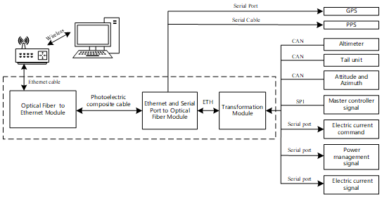
There are a large number of data exchange operations within the lower computer, and how they work together depends on smooth data transmission channels. Leveraging the concept of the internet of things (IoT), we connect various modules through Wi-Fi and ethernet channels to ensure seamless communication. As seen in Fig. 3, the data conversion module of the lower computer integrates various types of data, and it utilizes the lightweight TCP/IP stack (LwIP) to convert it into ethernet data for transmission. Meanwhile, using the serial port for file transmission is often limited due to the baud rate. To improve the speed of transmission and enhance the user experience of the software, ethernet file transmission is used as the primary transmission mode in this design. Reliable ethernet data transmission cannot be achieved without the transmission control protocol/internet protocol (TCP/IP). However, traditional TCP/IP systems are rarely used in small embedded systems. LwIP has the basic functions of TCP/IP and takes up less RAM, making it suitable for embedded systems with limited program space. LwIP also supports the dynamic host configuration protocol (DHCP), can dynamically assign IP addresses, and provides a special internal callback interface that effectively improves the program performance.
2.1.4 User operation based on USMART
The USMART module is used as a bridge between the user and the program in this design. Users can use each function of the program through serial port commands, achieving the effect of an external interruption, which is of great significance for systems requiring remote real-time control. Therefore, the USMART module is transplanted into the lower computer module to connect with the upper computer software and provide users with various control commands and parameters. This allows users to control the lower computer through the upper computer. It mainly includes the following functional functions, and Table 1 shows some of the functions and their respective features.
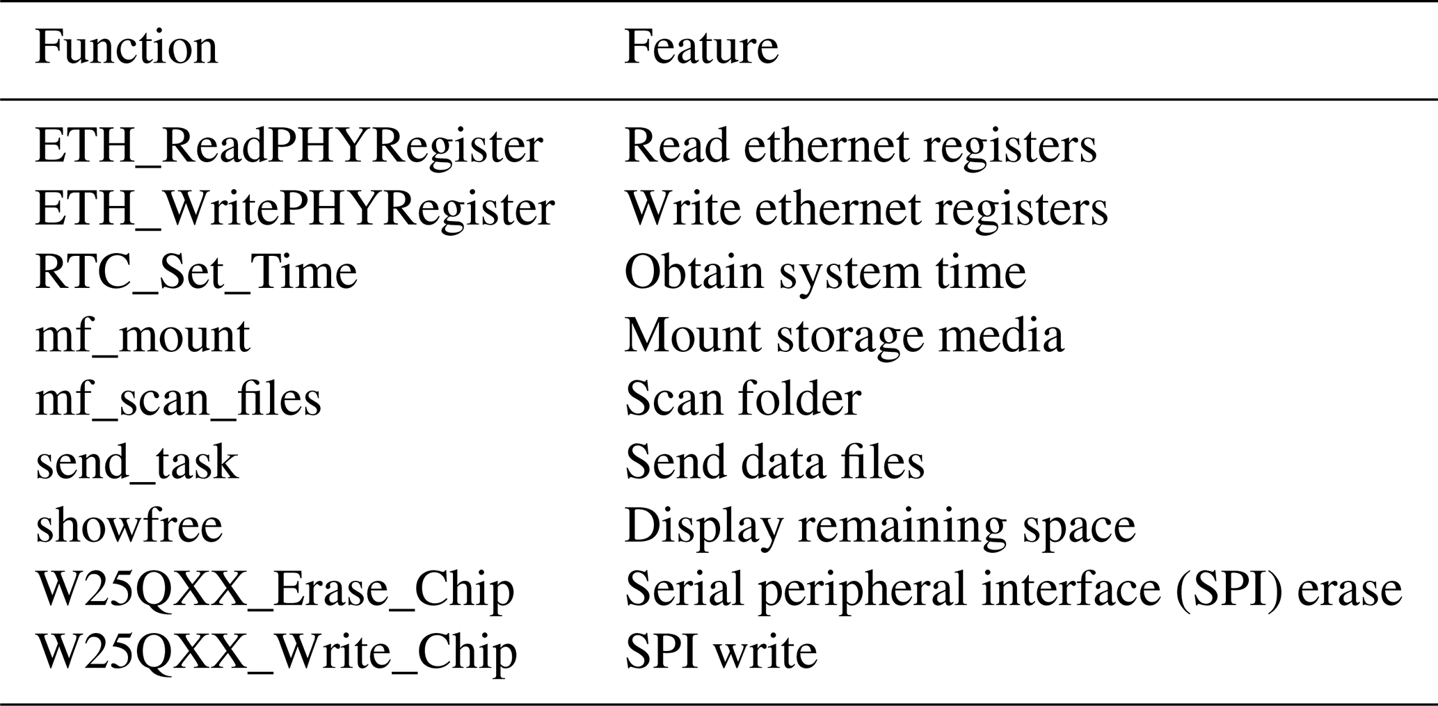
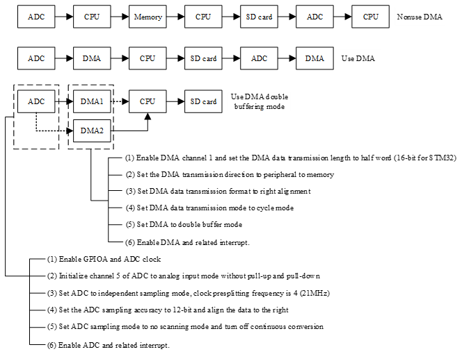
Figure 4Workflow of the ADC and DMA in different modes and the configuration of DMA and ADC.
2.2 Design of data acquisition module
2.2.1 Configuration of ADC and DMA
The main control unit is equipped with a 12 bit successive approach analog-to-digital converter (ADC) capable of measuring the signal of 16 external sources and 2 internal sources, and it also has direct memory access (DMA) capabilities. DMA allows for a quick transfer of the data between peripheral devices and memory, saving microcontroller unit (MCU) resources for other operations. In this design, the file storage and data acquisition are carried out simultaneously, and the double buffer mode of the DMA is used to solve this problem. This mode significantly reduces the MCU load, as shown in Fig. 4, which lists the workflow of data acquisition and storage in three cases, namely without DMA, using DMA, and using DMA double-buffer mode. The execution efficiency of the DMA double-buffer mode is higher than the other two modes.
2.2.2 Sampling rate configuration and data acquisition process monitoring
To ensure suitable sampling, the sampling rate should be adjusted according to the actual situation. In this design, the sampling rate of the ADC is controlled by the TIM3 timer. The trigger mode of the ADC is set to the “TIM3_TRGO” event, and the working state of the ADC is controlled by the overflow interrupt of the TIM3 timer. The overflow time of TIM3 can be changed by external input parameters, such as the frequency division number and reset value. The ADC sampling rate calculation formula is as follows, where ARR represents the reset value and PSC stands for the frequency division number of ADCCLK which is equal to 84 000 000/(ARR*PSC).
Additionally, an additional timer (TIM4) is used to capture the number of times that the ADC conversion is completed in a certain period. This allows for a real-time estimation of the ADC sampling rate and monitoring of the ADC's running state.
2.3 Design of file storage module
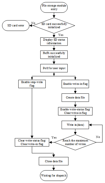
In the file storage module, the data files are stored on an SD card, and the management of the files relies on the FatFs file system. The porting process of the file system is not important, and the focus is on the method of realizing file storage. The storage process of the data file is illustrated in Fig. 5. The “write flag” and the “stop write flag” values are given by the serial port command, thus allowing users to start and terminate storage at any time. At the same time, the “write status flag” is used to mark the current state of the file storage module. Setting the maximum number of disk writes can control the size of each data file to about 10 MB. When the maximum number of disk writes is reached, the module will automatically close the current file and create a new file to continue writing. This ensures that when the system works for a long time, there are no problems caused by the size of a single data file.
2.4 Design of file transmission module
The file transfer module consists of ethernet data transmission and serial data transmission functions. Ethernet data transmission is based on LwIP, and serial transmission is used as a backup channel for ethernet transmission. The default baud rate for serial port transmission is 115 200 bps (bytes per second), and the default port number for ethernet transmission is 8087. The lower computer acts as the client, while the upper computer is the server.
2.4.1 Data file transmission of ethernet
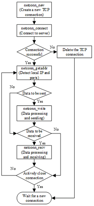
The LwIP protocol stack cannot be directly transplanted to the µC/OS-III system and requires encapsulation. LwIP has three commonly used programming interfaces, namely RAW, NETCONN, and socket interfaces. The RAW programming interface is often used when LwIP is used alone, while the NETCONN and socket interfaces are suitable to use with an operating system. The NETCONN interface is a structure abstracted from LwIP and is more concise than the socket interface. It does not waste memory when copying files. Therefore, the NETCONN programming interface is used in this design.
The flowchart of ethernet data file transmission with the NETCONN programming interface is shown in Fig. 6. In the process of data file reading, the length of the single data sequence should not be too small to reduce the impact of instruction judgment on transmission speed. When there is limited program space, the dynamic memory allocation method is necessary. The program uses the malloc() (memory allocation) function to dynamically allocate a data buffer of 512×32 bytes in SRAMIN (extended internal static random access memory or SRAM), which is automatically released after use. The size of the cache is a multiple of 512 bytes because the read and write object of the FatFs file system is a sector (512 bytes). After setting the length of a single data sequence, it is necessary to increase the ethernet data-sending window. If the default sending window is used, then packet loss will occur when the window length is less than the data length, which will affect the accuracy of the data.
2.4.2 Data file transmission and status control of serial port
As a key debugging tool and data communication interface, the importance of the serial port is self-evident. In this design, CH340G is used as the serial port connection to the USB chip because the MCU needs to communicate with the host computer through the USB interface. The CH430G chip can be compatible with RS485, RS232, and other interfaces through the external-level translator. As a full-speed USB device interface, it is compatible with USB2.0 and serial port applications under the Windows operating system.
With the hardware environment in place, the configuration of the serial port in the program follows these steps: (1) enable the GPIOA clock and enable the USART1 clock; (2) reuse GPIOA9 and GPIOA10 for USART1; (3) enable GPIOA9 and GPIOA10; (4) set the baud rate of the serial port to 115 200 bps; the data bit is 9, the stop bit is 1, and the check mode is odd check; (5) enable the serial port transceiver mode; and (6) write the interrupt function of USART1 and enable the interruption.
In the process of a serial port configuration, special attention should be paid to the nine data bits, where the eighth bit is the data and the ninth bit is the parity check bit. The parity check mode corresponds to the single-chip microcomputer. After completing the above configuration process and main program preparation, the MCU can perform analog signal acquisition, serial port transmission, file management, and other functions.
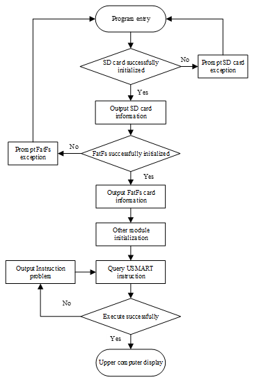
Figure 7 shows the flowchart of using the serial port to control the lower computer. After the initialization of the ADC/DMA, file system, SD card, and other modules, the MCU can realize the corresponding functions through the commands and parameters provided by USMART. However, if the command or parameter is incorrect, then the program will automatically return the error reason and output it to the serial port to prompt the user to verify it.
The upper computer that is receiving software for the marine controlled-source online transmitter system is designed using the Python programming language. Python is a cross-platform, high-level programming language with good portability and perfect functional modules, which can meet the needs of online data transmission. Additionally, Python has unique advantages in machine learning and data analysis. Currently, the host software is primarily responsible for segmenting the received data and handing it over to the corresponding programs for processing. In the future, the Python platform can be used to analyze and learn the data in the file, thereby providing real-time prediction and early warning for marine experiments during software iteration.
3.1 Python programming environment construction
The upper computer program is developed in the PyCharm integrated development environment, and its configuration process is shown in Table 2.
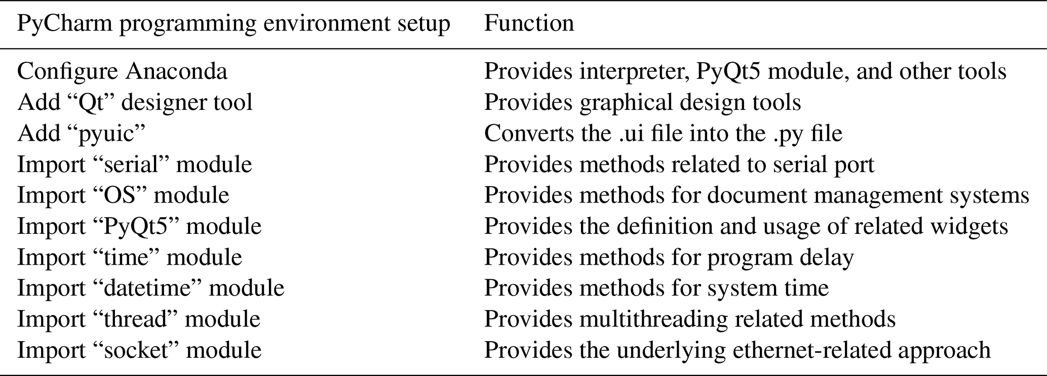
3.1.1 Configure Anaconda interpreter
The most important thing to build in the PyCharm environment is the choice of interpreter. Anaconda is an open-source package manager. It contains more than 100 packages and dependencies, such as Pandas (a toolset for analyzing structured data), NumPy (a module that supports a large number of dimensional arrays and matrix operations and also provides a large number of mathematical function libraries for Array Operations), and PyQt (a toolkit for creating graphical user interface (GUI) applications). This design uses Anaconda as the interpreter environment for PyCharm and uses PyQt5 contained in Anaconda for the UI (user interface) design.
3.1.2 Import of function modules
This design needs to transmit data files and control commands through a serial port, so serial communication is the most basic function. As a Python module, “serial” integrates most of the commonly used serial port configuration methods, so it is necessary to import the serial module into the project. We use the “import serial” statement to import the serial module.
This design needs to extract the data files in the lower computer to the PC, so the operating system (OS) file management module is essential. Through the method of the “OS” module, a series of operations such as adding, deleting, and rewriting can be realized. We use the “import OS” statement to import the OS module.
PyQt5 is a Python module under the “Qt” framework, which contains hundreds of classes and thousands of functions and methods. This design mainly uses two modules in PyQt5; one is “Qt Core” (including core non-GUI functions, such as process time, files and directories, various data types, streams, URL, MIME (multipurpose internet mail extensions) types, threads, and processes). The second is “Qt Widgets” (this module contains the classic desktop-style user interface and provides a set of UI element classes). We use the “PyQt5 import Qt Widgets” and “from PyQt5.QtCore import Qt timer” statements, respectively, to import the module.
This design needs to make the real-time clocks (RTC) of the MCU synchronize with PC, so it needs to obtain the system time of upper computer for the MCU. The main function of “datetime” module is to enable the program to obtain the current time of the system and output it in the specified data format. In order to import, the datetime module needs to use the “import datetime” statement.
This time module provides the function of program delay, which is mainly used to reserve sufficient time for serial transmission. We use “import time” to import the time module.
3.2 Use of multithreading
The smooth operation of the upper computer software depends on the repainting of the UI. However, both the serial file transfer and ethernet file transfer will interrupt the redrawing process, leading to software death. In order to solve this problem, we need to use multithreading in the program.
Multithreading does not mean that multiple tasks run at the same time. Rather, the CPU switches between different tasks quickly as needed and achieves the effect of several tasks being executed concurrently. Under the Windows OS platform, the independence of each task in a multiple process is better than that in multithreading, but its system occupancy is much higher than that in multithreading. Therefore, this program uses multithreading. As shown in Fig. 8, the program is mainly divided into the following three threads: (1) the main thread, which is mainly responsible for command processing and UI redrawing; (2) the serial port transmission thread, which mainly responsible for the construction of serial port channel and the receiving of the serial command and data file; and (3) the ethernet thread, which is mainly responsible for the construction of ethernet channel and ethernet file transmission.
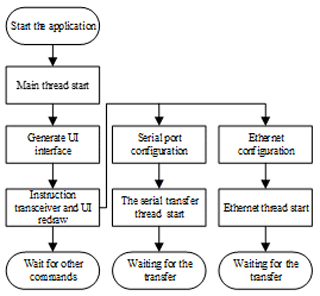
Through the “thread(target = thread name)” method, it is possible to create the process. Through the “threading.Event” method, it is possible to set flag events for each thread to control the start or stop of the program.
3.2.1 Construction of serial transmission thread
The serial module is needed to build the serial port channel for the upper computer software. The construction process is divided into the following steps: (1) use the “serial.Serial” method to create a serial port object; (2) use the “self.ser.port” method to set the serial port to be opened, use the “self.ser.baudrate” method to set the baud rate, and use the “self.ser.bytesize” method to set the number of bits of data transmission, the “self.ser.stopbits” method to set the stop bit, and the “self.ser.parity” method to set the parity bit; and (3) use the “try” statement to call the “self.ser.open” method. Then, open the serial port according to the above settings. If the serial port can be opened, then it will display that the serial port has been opened and enable the closing of the serial port button. Then, set the open serial port button to the unselected state. If it cannot be opened, then a port error is displayed.
3.2.2 Ethernet thread construction
The upper computer software requires the socket module to build the server. The construction process is divided into the following steps: (1) use the “socket.gethostname” method to obtain the local IP address; (2) use the “socket.socket(AF_INET, SOCK_STREAM)” method to create the ethernet interface; (3) use the “sk.bind” method to bind the local address; (4) use the “sk.setsockopt(SOL_SOCKET, SO_RCVTIMEO, 1000)” method to set the timeout to 1000 ms; and (5) use the “sk.accept” method to wait for the client to connect.
3.3 UI design based on Qt designer
To design a UI in PyQt5, it can be achieved by writing the code directly or by using the graphical design interface of Qt designer. When compared to directly achieving the UI through the code, the graphical interface can be more intuitive, showing the relationship between the various controls, and the designer will have a better grasp of the overall interface. Qt designer is used to design the UI and can be added to PyCharm's external tools from the Anaconda package. The UI design results are shown in Fig. 9.
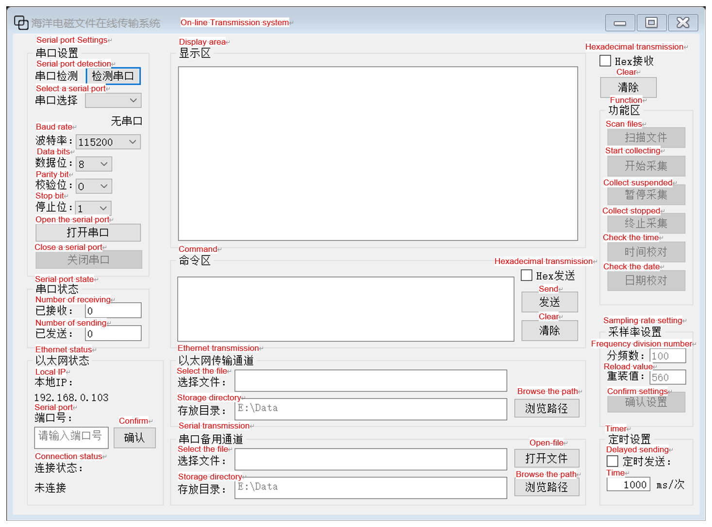
Figure 9User interface.
The .ui file generated by Qt designer cannot be used directly. The pyuic extension is needed to make Qt designer and Python work together. pyuic is an automated scripting tool that can convert .ui files into executable .py files for Python.
3.4 Compilation of function
3.4.1 Create class
After using Qt designer to complete the design of UI, the generated .ui file is saved in the PyCharm project directory, and the .ui file is converted to a .py file by using pyuic. This file will contain a file called “UI_Form”, which contains the basic information of the designed UI. In their own projects, the UI_Form class is imported as a module, and then a subclass “My_Client” is created. It inherits the UI_Form properties, and then an instance of the UI is built.
3.4.2 Define methods and connect to widgets
In order to implement the functions in a UI, each widget needs to be given some corresponding methods. The “initialize” function is defined, and the “connect” method is used to connect the function and the widget by using the syntax “self.widget_name.signal.connect (self.function_name)”.
For button widgets such as “self.open_button.clicked.connect(self.port_open)”, this means that when the “open_button” is pressed, the program will execute the “port_open” function.
For text widgets such as “self.s1__box2.currentTextChanged.connect(self.port_imf)”, this means that when the value of “s1_box2” is changed, the program will execute the “port_imf” function.
For check box widgets such as “self.timer_send_cb. stateChanged.connect(self. data_send_timer)”, this means that when the checkbox is selected, the program executes the “data_send_timer” function.
According to the above method, each widget is given a corresponding function.
3.4.3 Write the function corresponding to each widget
Table 3 shows the names and functions of each widget in the program. The following is a brief introduction to the realization process of several main functions.
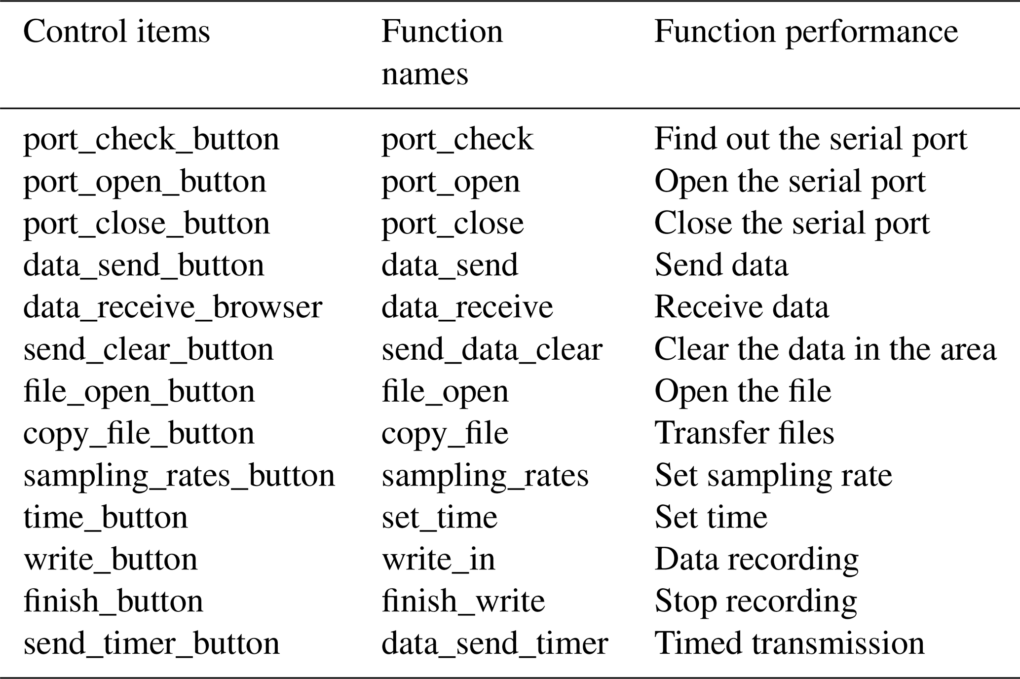
The “port_close” function is used to close the current serial port. This function first stops the timer and then stops transferring the contents of the buffer. It then uses the “try” statement to call the “self.ser.close” method to close the serial port. Finally, it clears all the buffer areas and display area contents, resets all widgets to the default state, and changes the serial port status to “closed”.
The “data_send” function sends the content of the command area through the serial port. This function first uses the “toPlainText” method to format the text of the command area to the local variable “input_s” when the serial port has been opened. It then checks whether the hexadecimal sending status bar is selected, and if so, the input_s variable will be converted into a hexadecimal format. After processing the data, the function uses the “self.ser.write” method to write it to the serial port.
The “data_receive” function displays the data sent by the lower computer to the host computer in the receiving area through the serial port. This function first uses the “self.ser.inWaiting” method to return the length of the data in the buffer and stores it in “num”. It then uses the “self.ser.read” method to read out the data. In this process, the value of num is recorded and accumulated to obtain the total volume of data received. The “textcursor” method is used to obtain the position of the cursor in the receiving area, and at the same time, the “movePosition.end” method is used to move the cursor target to the bottom (to ensure that the cursor remains at the end of the data write).
The “send_data_clear” function uses the “setText” method to set the contents of the command area to an empty string.
The “receive_data_clear” function uses the setText method to set the contents of the display area to an empty string.
The “file_open” function uses the toPlainText method to obtain the file name specified in the address bar, and the content of the command area is set to the function which the lower computer can recognize to open the file. The “ser.write” method is used to send the command.
The “copy_file” function uses the “os.chdir” method to change the program running directory to the specified location, and the files specified in the lower computer are extracted to the upper computer. The “ser.inWaiting” method is used in the process of transmission to determine whether the transmission is completed, and a prompt is given in the command area after the transmission is completed.
The “sampling_rates” function uses the “self.text” method to obtain the frequency division number and the reload value input by the user. The current sampling rate is calculated by the formula ) and displayed in the command area. Finally, the command of changing the sampling rate is sent to the lower computer.
The properties in the “init” function are automatically generated when the class is instantiated. The “super(My_Client, self).init” method is used to call the function from its parent class to complete initialization. The “setupUi” method from the parent class is called to make its UI layout according to the designed UI. The name of the form is set to “marine electromagnetic file online transmitter system”, using the “setWindowTitle” method. The serial.Serial method is used to configure the API functions related to the serial port.
After the above process, we have created a class that meets the expected function. For Python, it is equivalent to completing a drawing. Next, we should instantiate it. First, the “QtWidgets.QApplication(sys.argv)” method is used to create a form application with parameters (“sys.argv” is the bridge between the program and the external parameters and points the external action to the program). Then, the designed class My_Client is used to create an instance named “my_show”, and the “show” method is used to visualize the program window. Finally, the “sys.exit(app.exec_())” method is used to leave an exit for the program.
Figure 10 shows the actual situation of the joint test of the lower computer and the upper computer.
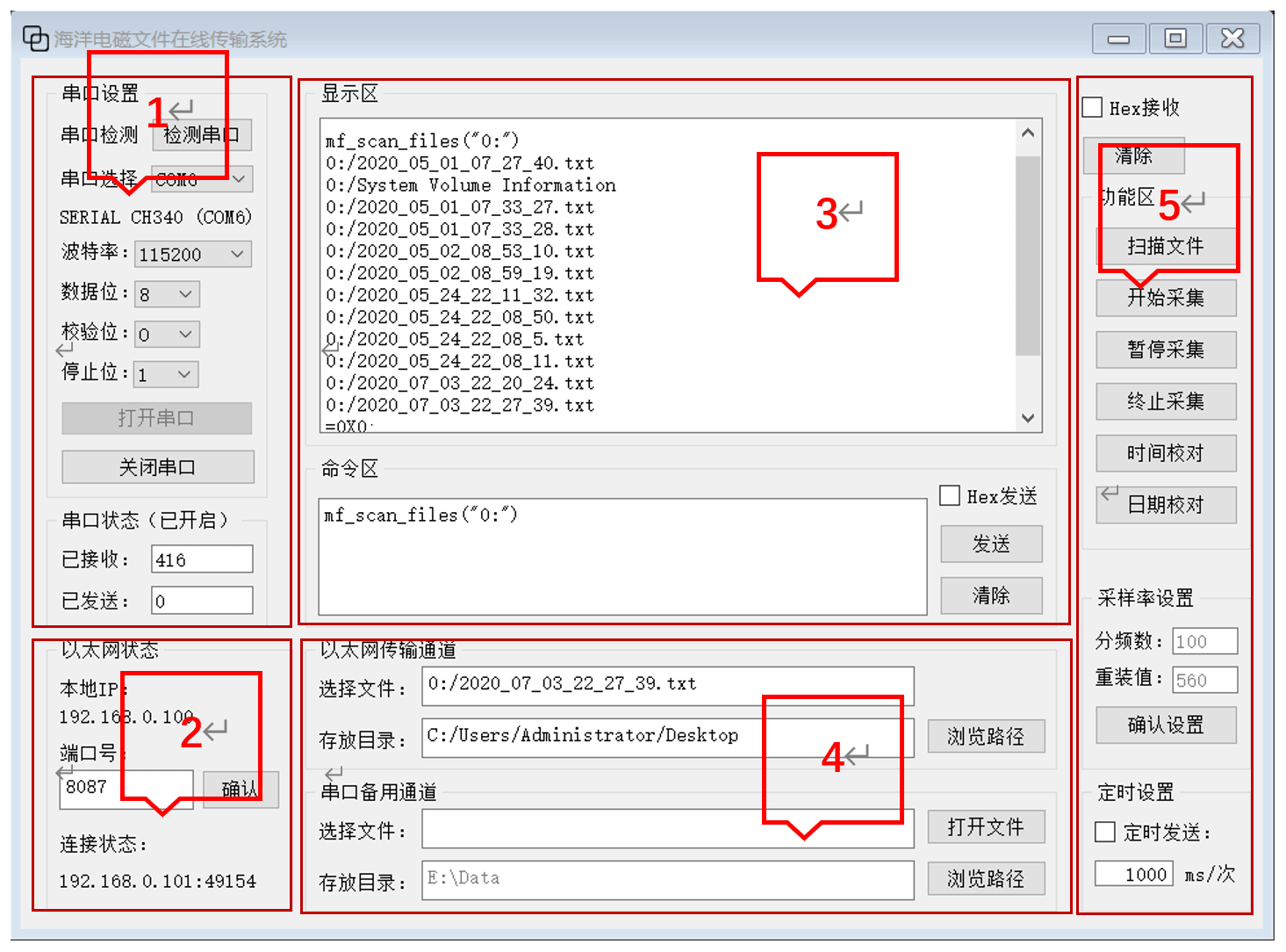
Figure 10Software running status.
Area 1 is the serial port configuration area, where the baud rate is set to 115 200 bps, the data are set to 8 bit, the verification mode is set to ODD, and the stop bit is set to 1. After the configuration is completed, the user can see that the serial port is successfully opened, and the port is set to COM6.
Area 2 is the ethernet configuration area, where the local IP is automatically obtained by the software, and the port number is set to 8087. After clicking the confirm button, the user can see the remote IP and port in the connection status area.
Area 3 is the command area and display area. In Fig. 10, it shows the file query function, and the display area shows all files and folders under the root directory of the SD card.
In order to verify the accuracy of data transmission, it is necessary to compare the data files stored in the SD card with those extracted to the upper computer. As shown in Figs. 11 and 12, we can see that the byte difference between the two files is zero; that is, the two files are the same. After many tests, the accuracy of the file's online transmitter system in this paper is proved.
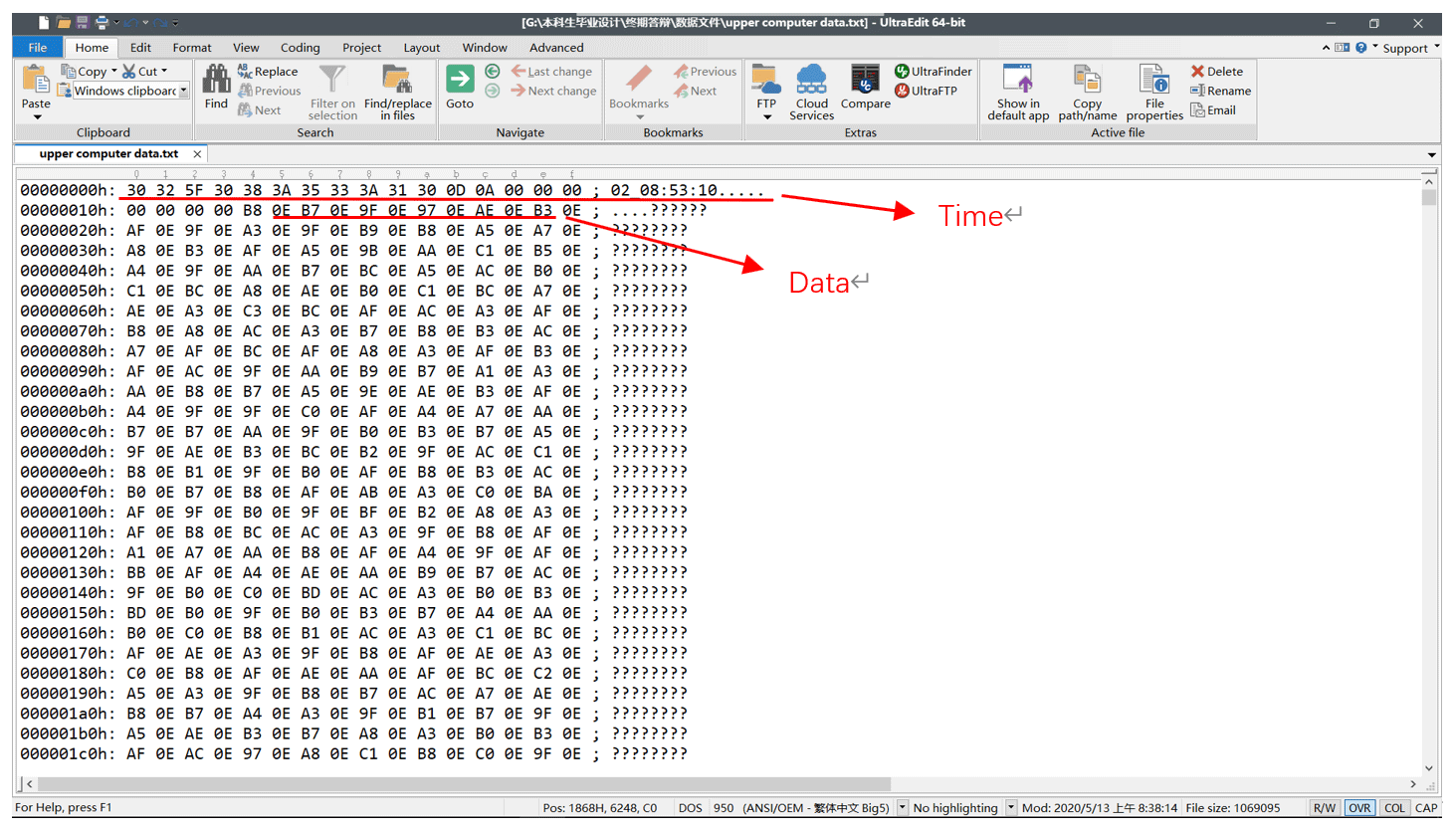
Figure 11Data files extracted to upper computer (UltraEdit).
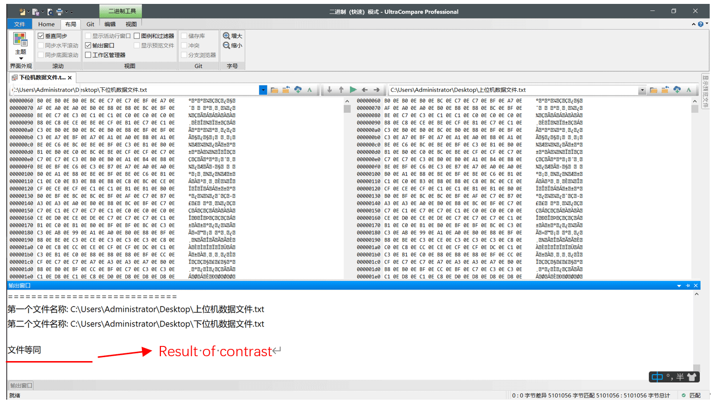
Figure 12Comparison of data files (UltraCompare).
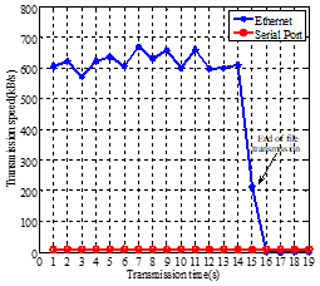
In the transmission process of a standard data file with a size of 10 MB, we tested its transmission rate, including the serial transmission rate and ethernet transmission rate. The ethernet transmission rate is much higher than the serial transmission rate. The average ethernet transmission speed is 600 KB s−1, compared to the 10 KB s−1 for the serial communication rate. The data file transmission can be completed in about 15 s, as shown in Fig. 13; however, it needs to be emphasized that the STM32 has a clock frequency of 168 MHz, and it can only support up to 100 Mbps ethernet. Furthermore, due to the numerous tasks it needs to handle internally, it does not run the ethernet transmission thread separately and is thus unable to achieve the ideal transmission rate. In our offshore operations, the sampling rate is 150 Hz, and the current transmission speed is already able to meet our data transmission needs.
Compared with traditional data transmission methods, online transmission has significant advantages in real-time data transmission. The data can be transmitted in real time, allowing for immediate decision-making and action to be taken. This is especially important in marine operations, where timely information can prevent accidents.
The technical scheme of the marine controlled-source electromagnetic current file online transmitter system uses STM32 as the lower computer to implement the functions of data acquisition, data storage, and file transmission. The upper computer software is designed using Python language, allowing users to control the single-chip microcomputer and acquire data files through the upper computer software.
In the lower computer module, the ADC is used to accurately collect the analog current signal, and the DMA double buffer mode is used in the acquisition process, which greatly improves the utilization of CPU. The FatFs file system is used to save the collected data to the SD card in the form of a file. After receiving the command from the upper computer, the data file can be transmitted to the upper computer through the serial port and ethernet.
In the receiving software of the upper computer, Python language is used to realize the basic serial communication and ethernet communication functions, and the UI design of the upper computer software is completed with the help of Qt designer. The software uses multithreading technology to solve the problem of program death in the process of file transmission.
In the joint test of the upper computer and the lower computer, the serial communication, file transmission, time correction, data acquisition, and other functions are tested. The final test result shows that the online transmitter system can run stably for a long time, and the upper computer can successfully control the lower computer. Data files can be transferred from the lower computer to the upper computer, and the ethernet file transfer rate can reach 600 KB/s, which can meet the needs of marine operations. By using data comparison software, the difference between the data files in the SD card and the data files transferred to the upper computer is compared, and the results prove the accuracy of the data transmission.
The online system for marine controlled-source electromagnetic data not only provides great convenience for marine experiments but also provides security for the experimental data. In the future, software optimization can take advantage of Python language in machine learning and data analysis so that it can provide a real-time visual interface and complete warning and prediction; moreover, the online transmitter system will provide greater assistance for marine experiments.
No data sets were used in this article.
MD is the major scientific researcher. MW is the project applicant and has provided the experimental conditions. ND and XM, as the research assistants, have completed the data-processing work. CTW is the project leader and primarily responsible for scheme design, specific functionality implementation, and other works.
The contact author has declared that none of the authors has any competing interests.
Publisher's note: Copernicus Publications remains neutral with regard to jurisdictional claims in published maps and institutional affiliations.
This work has been supported in part by the Dedicated Fund for Marine Economic Development in Guangdong Province (grant no. GDNRC[2023]40), the MOST Special Fund from the State Key Laboratory of Geological Processes and Mineral Resources, China University of Geosciences, and the National Key Technologies R&D Program (grant nos. 2022YFC2807900 and 2016YFC0303100).
This paper was edited by Ralf Srama and reviewed by three anonymous referees.
Chen, K., Jing, J. E., and Wei, W. B.: Numerical simulation and electrical field recorder development of the marine electromagnetic method using a horizontal towed-dipole source, Chin. J. Geophys., 56, 3718–3727, https://doi.org/10.6038/cjg20131113, 2013.
Chen, K., Deng, M., Ping, M., Yang, Y., Luo, Q., Yi, X. H., and X. P.: A near-seafloor-towed CSEM receiver for deeper target prospecting, Terr. Atmos. Ocean. Sci., 31, 565–577, https://doi.org/10.3319/TAO.2020.08.03.01, 2020.
Connell, D. and Key, K.: A numerical comparison of time and frequency-domain marine electromagnetic methods for hydrocarbon exploration in shallow water, Geophys. Prospect., 61, 187–199, https://doi.org/10.1111/j.1365-2478.2012.01037.x, 2013.
Constable, S.: Marine electromagnetic methods – A new tool for offshore exploration, Lead. Edge, 25, 438–444, https://doi.org/10.1190/1.2193225, 2006.
Constable, S.: Ten years of marine CSEM for hydrocarbon exploration, Geophysics, 75, 75A67–75A81, https://doi.org/10.1190/1.3483451, 2010.
Constable, S., Kannberg, P. K., and Weitemeyer, K.: Vulcan: A deep-towed CSEM receiver, Geochem. Geophy. Geosy., 17, 1042–1064, https://doi.org/10.1002/2015GC006174, 2016.
Duan, N., Wang, M., Wang, G., Yu, P., Deng, M., and Li, X.: Research on the isolation and collection method of multi-channel temperature and power supply voltage under strong marine controlled source EMI, IEEE Access, 7, 6400–6411, https://doi.org/10.1109/ACCESS.2018.2889887, 2018.
Li, S. Y., Gu, C. Y., Yang, J. Y., Zhang, Y., Diao, S., and Ji, Y. J.: A review of marine controlled-source electromagnetic data preprocessing technology, AIP Adv., 12, 090701, https://doi.org/10.1063/5.0090082, 2022.
Li, Y. G. and Constable, S.: Transient electromagnetic in shallow water: insights from 1D modeling, Chin. J. Geophys., 53, 37–742, http://en.dzkx.org/article/doi/10.3969/j.issn.0001-5733.2010.03.029, 2010.
Liu, L., Yin, C. C., Liu, Y. H., Qiu, C. K., Huang, X., and Zhang, B.: Spectral element method for 3D frequency-domain marine controlled-source electromagnetic forward modeling, Chin. J. Geophys., 61, 756–766, https://doi.org/10.6038/cjg2018L0308, 2018.
Pethick, A.: Macro-parallelisation for controlled source electromagnetic applications, J. Appl. Geophys., 124, 91–105, https://doi.org/10.1016/j.jappgeo.2015.11.013, 2016.
Wang, M., Zhang, H. Q., and Wu, Z. L.: Marine controlled source electromagnetic launch system for natural gas hydrate resource exploration, Chin. J. Geophys., 56, 3708–3717, 2013.
Wang, M., Deng, M., Wu, Z., Luo, X., Jing, J., and Chen, K.: The deep-tow marine controlled-source electromagnetic transmitter system for gas hydrate exploration, J. Appl. Geophys., 137, 138–144, https://doi.org/10.1016/j.jappgeo.2016.12.019, 2017a.
Wang, M., Deng, M., Wu, Z. L., Luo, X. H., Jing, J. E., and Chen, K.: New type deployed marine controlled source electromagnetic transmitter system and its experiment application, Chin. J. Geophys., 60, 4253–4261, https://doi.org/10.6038/cjg20171113 10.6038/cjg20171113, 2017b.
Wang, M., Deng, M., Yu, P., Yin, C., Chen, K., and Luo, X. H.: High-power time-frequency transmission and multi-chain cable multi-component electromagnetic system for deep-water exploration, Chin. J. Geophys., 65, 3664–3673, 2022.
Wang, S., Constable, S., Reyes-Ortega, V., and Rychert, C. A.: A newly distinguished marine magnetotelluric coast effect sensitive to the lithosphere–asthenosphere boundary, Geophys. J. Int., 218, 978–987, https://doi.org/10.1093/gji/ggz202, 2019.
Xu, C. S., Wang, M., Zhang, N., and Jiang, Y. L.: The development of MCSEM transmitter on-board monitoring and controlling unit, Prog. Geophys., 32, 414–420, 2017.
Zhao, W. Q., Jing, J. E., Yang, J., Zhao, Q. X., and Luo, X. H.: Development of Marine Controlled Source Electromagnetic Data Preprocessing Software Based on Duilib Library, Comput. Tech. Geophys. Geochem. Explor., 43, 261–268, 2021.