the Creative Commons Attribution 4.0 License.
the Creative Commons Attribution 4.0 License.
Development of an internet-of-things-based controlled-source ultrasonic audio frequency electromagnetic receiver
Zucan Lin
Keyu Zhou
Xiyuan Zhang
Xinchang Wang
Hui Zhang
Feng Liu
Electromagnetic exploration, characterized by its low cost, wide applicability, and high operational efficiency, finds extensive applications in fields such as oil and gas exploration, mineral prospecting, and engineering geology. Traditional controlled-source electromagnetic detection methods are typically confined to operating frequencies below 250 kHz, resulting in insufficient detection accuracy for applications such as shallow- and intermediate-depth exploration, thereby constraining their performance in high-resolution imaging. To address these challenges, we propose a controlled-source ultrasonic audio frequency electromagnetic receive system based on the internet of things (IoT). We investigate cascaded digital filtering and sampling techniques to extend the receiver's sampling rate range, thereby elevating the operating frequency of controlled-source electromagnetic acquisition from the conventional maximum of 250 kHz to 1 MHz. The receiver achieves a sampling rate of up to 2.5 MHz, comprising three magnetic field measurement channels and two electric field measurement channels. The instrument is compact, lightweight, and capable of real-time data storage locally and real-time data transmission to an upper computer. Additionally, IoT technology is introduced, leading to the design of a cloud-based real-time remote control and data acquisition scheme. Experimental results demonstrate the stability of the instrument, meeting the requirements of field exploration.
- Article
(6341 KB) - Full-text XML
- BibTeX
- EndNote
Electromagnetic exploration, renowned for its low cost, widespread applicability, and operational efficiency, is extensively utilized in fields such as oil and gas exploration, mineral prospecting, and engineering geology (Teng et al., 2022; Wang et al., 2022; Chun-lei et al., 2022; Zhou et al., 2021a; Wang et al., 2023). The electromagnetic exploration method (EM) can be categorized into time domain electromagnetic method (TEM) and frequency domain electromagnetic method (FEM). The FEM (Peng et al., 2024) primarily encompasses magnetotellurics (MT), which employs natural field sources, and controlled-source magnetotellurics (CSMT), which utilizes artificial field sources. CSMT is commonly applied in geothermal resource exploration (Aykaç et al., 2015; Zhang et al., 2022), mineral resource exploration, hydrological surveys, engineering geology, and other fields (Tang and Wang, 2023; Liu et al., 2022; Guo et al., 2020; Farzamian et al., 2019). CSMT method can be classified into controlled-source audio frequency magnetotellurics (CSAMT) and controlled-source radio frequency magnetotellurics (CSRMT) based on different operating frequencies. CSAMT (Zhou et al., 2021b) typically operates within the frequency range of 0.1 Hz to 10 kHz, with exploration depths ranging from tens of meters to 2–3 km, making it suitable for exploring geothermal and mineral resources in the subsurface. CSRMT (Xu et al., 2014) operates within the frequency range of 10 kHz to 250 kHz. Traditional controlled-source electromagnetic detection methods are usually limited to operating frequencies below 250 kHz, which poses challenges in achieving adequate detection accuracy for applications such as shallow and intermediate-depth exploration, thereby restricting its performance in high-resolution imaging.
Additionally, a single transmission source and a single-directional transmission strategy are typically employed in existing controlled-source electromagnetic exploration methods. This makes them susceptible to shielding effects from underground resistive bodies, limiting the comprehensive perception of electromagnetic field signals and thereby reducing the effectiveness of exploration. Moreover, due to the use of a single-directional transmission method, transmission efficiency is low, further impacting the accuracy of exploration. Therefore, the presence of these issues urgently necessitates an innovative controlled-source electromagnetic exploration method to enhance operating frequencies, improve detection accuracy, and address the obstacles to efficient exploration present in traditional methods.
Simultaneously, the electromagnetic receivers widely used in exploration commonly suffer from low sampling rates and typically utilize data storage media such as SD cards, which cannot meet the demands for multi-channel, high-sampling-rate, and long-term continuous data acquisition. To address these issues, we propose a controlled-source ultrasonic audio frequency electromagnetic receiver with a working frequency range of 1 Hz to 1 MHz, which can further improve accuracy in shallow- to intermediate-depth exploration. The device is portable and capable of instantly storing data locally, while also supporting real-time data transmission to a central processing unit. Additionally, by integrating internet-of-things (IoT) technology, we have developed a cloud-based solution that enables real-time remote control of the device and data collection functionalities.
The magnetotellurics (MT) method was first proposed by the French scholar Cagniard in 1953 (Cagniard, 1953). CSMT evolved from audio magnetotellurics (AMT). In 1975, Goldstein and Strangway introduced the use of artificial electrical sources in AMT and discussed their application in mineral exploration (Goldstein and Strangway, 1975). The emergence of CSMT has addressed the instability of the field source and the difficulty in obtaining high-signal-to-noise-ratio data in AMT, greatly advancing the development of electromagnetic exploration. However, it has also introduced a series of source-related issues such as susceptibility to terrain effects and non-planar wave effects.
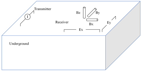
A typical schematic diagram of a CSMT device is shown in Fig. 1, and the scalar apparent resistivity calculation method is represented by Eq. (1) (Zhang et al., 2021; Rong and Liu, 2022; Yu et al., 2023). Here, E and H represent the mutually perpendicular horizontal components of the electric and magnetic fields. In AMT, the field source is the electromagnetic field excited by distant lightning, which can be approximated as a plane wave in the exploration area. However, when artificial sources are used for exploration, as the sources are closer to the survey area, not all electromagnetic waves in the exploration area can be simply regarded as plane waves. In 1982, Sandberg described the distribution of electromagnetic fields excited by artificial sources in a uniform half-space and pointed out that the electromagnetic waves at a position could be considered plane waves, and the apparent resistivity calculated according to Formula 1 could approach the true resistivity only when the receiver–transmitter distance was greater than 3 times the skin depth (receiver located parallel to the transmitter) or 5 times the skin depth (receiver located in the same direction as the transmitter). This phenomenon is known as the near-field effect (Sandberg and Hohmann, 1982). There are typically two ways to avoid the near-field effect: one is to deploy stations reasonably to exclude data from the near-field area, while the other is to correct data using near-field correction algorithms to achieve full-area detection.
Here, μ represents the magnetic permeability of the medium, while ω represents the angular frequency of the electromagnetic wave.
3.1 Overview of the architecture
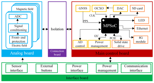
The overall hardware structure of the receiver is illustrated in Fig. 2, comprising the interface board, analog board, connection board, and main control board. The interface board serves as the bridge between the internal and external components of the instrument, integrating sensor interfaces, power interfaces, communication interfaces, indicator light interfaces, and keypad interfaces. The sensor interfaces consist of magnetic field sensors and electrode terminals, with their connections linked to the analog channel input terminals on the analog board. The power interface is responsible for supplying external 12 V power, which is distributed through the power distribution network to the entire system. The communication interface, indicator lights, and keypad facilitate human–machine interaction, with their internal wiring connected to the multiprocessor system-on-chip (MPSoC) design of the main control board. Additionally, the interface board has functions such as overcurrent protection and battery monitoring. The digital interfaces of the power monitoring chip and power control chip on the interface board are also connected to the MPSoC on the main control board.
On the connection board, there is a magnetic coupling isolation module, which connects to the digital signal ports of both the analog board and the main control board. It is responsible for isolating the digital and analog parts, severing electrical connections to reduce interference from the digital part on the analog signals.
3.2 Design of the analog board
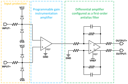
The analog board is designed with five analog channels, each responsible for conditioning and analog-to-digital conversion (ADC) of signals from two electric field components and three magnetic field components. As shown in Fig. 5, the signal conditioning circuit mainly consists of input protection circuits, programmable gain amplifiers, single-ended to differential conversion circuits, and anti-aliasing filtering circuits. We employ the AD8253 amplifier (Yuan et al., 2016) as the programmable gain amplifier, which boasts a high slew rate of up to 20 V µs−1, meeting the bandwidth requirements for ultrasonic data acquisition. It provides programmable gains from 1 to 1000, enhancing the circuit's capability to capture weak signals. The analog-to-digital conversion circuitry includes the AD7760 (Zhang et al., 2015) analog-to-digital converter and its peripheral circuitry, with its digital interface connected to the MPSoC on the main control board via the connection board. The AD7760 is capable of outputting 24-bit precision sampling data at a maximum frequency of 2.5 MHz.
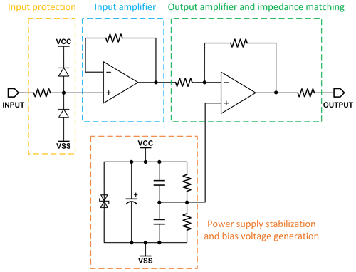
As shown in Fig. 3, the electric field sensor uses an active transmission line with a front-end amplifier, connected to a metal rod buried in the soil. The magnetic field sensor uses an inductive magnetic sensor. The input circuit for the signal is protected by Schottky diodes and current-limiting resistors, as shown in Fig. 4.
3.3 Design of main control board
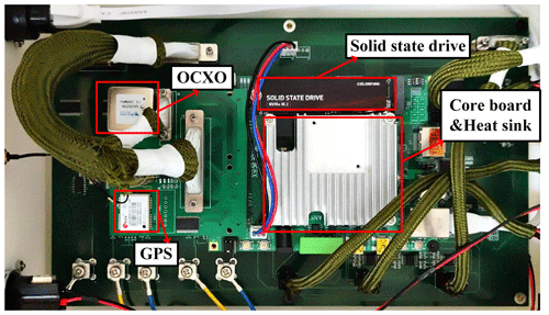
We employ the XCZU3EG MPSoC as the primary control chip (Khandelwal and Shreejith, 2022), and the physical appearance of main control board is depicted in Fig. 6. Internally, XCZU3EG consists of two internal components, ARM (advanced RISC machine) and FPGA (field programmable gate array), with both having distinct responsibilities. The FPGA portion primarily manages the analog board for ADC, receives and parses converted data, processes GNSS data, calibrates the oven-controlled crystal oscillator (OCXO), and controls system power. On the other hand, the ARM portion handles the overall workflow control of the entire acquisition station, human–machine interaction, and data storage. Communication between the ARM and FPGA sections occurs via the internal AXI (advanced extensible interface) bus, allowing the ARM part to configure acquisition parameters and control acquisition start and stop by accessing FPGA registers. After parsing by the FPGA, the analog-to-digital converted data is transmitted to the ARM section in the form of data streams, stored onto external solid-state drives, and transmitted in real time to the host computer via Ethernet. The ARM part also manages functions related to buttons and LEDs and facilitates remote real-time monitoring through data transmission with a 4G module. Additionally, the main control board includes circuits for storing program code on a microSD card, storing acquisition data on solid-state drives, providing communication via gigabit Ethernet, ensuring time synchronization via GNSS, and providing stable clock signals through OCXO. The solid-state drives offer read and write speeds of up to 3.5 GB s−1, meeting the requirements for real-time storage of multi-channel high-sampling-rate full waveforms in ultrasonic data acquisition (40 MB s−1). The OCXO-related circuits consist of a DAC (digital-to-analog converter) circuit and a voltage-controlled OCXO, where the DAC generates a voltage signal to calibrate the voltage-controlled OCXO.
3.4 The 4G module
To ensure efficient and reliable data transmission and remote management in our system, we have selected the cost-effective USR-G771-GL 4G DTU (data transfer unit) module (Zhang and Wang, 2022), manufactured by USR IoT. This module supports multiple 4G LTE frequency bands worldwide, ensuring extensive network coverage and compatibility. Moreover, it offers high-speed data transmission and extremely low communication latency, enabling real-time data processing and rapid response. The USR-G771-GL module is an ideal choice for the digital transformation and network expansion of our system, meeting the stringent requirements of the modern industry for high-speed, stable, and remote communication.
Equipped with standard serial port interfaces, the module seamlessly connects to the main control unit, facilitating seamless data exchange. This simple connectivity greatly promotes the intelligent upgrading of traditional serial port devices, providing them with wireless network access capabilities. Whether in industrial automation, intelligent transportation systems, or environmental monitoring, the module demonstrates outstanding performance.
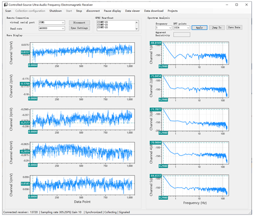
By employing the USR-G771 module, users can achieve remote monitoring and management of the receiver, enabling centralized data collection and control regardless of the receiver's location. This capability significantly enhances operational efficiency, reduces maintenance costs, and increases system flexibility. The connection topology is illustrated in Fig. 7, and the interface of the remote operating system is shown in Fig. 8.
3.5 Programming design
3.5.1 Lower-computer program framework
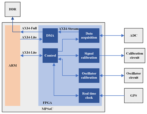
The FPGA part of the MPSoC is a programmable logic device and serves as the main component of the digital circuitry in the receiver. The program structure of the FPGA is expected to include various modules, as illustrated in Fig. 9.
The data acquisition module is responsible for configuring the ADC's acquisition parameters, controlling ADC start and stop, and retrieving and parsing ADC data. It consists of five identical ADC control sub-modules, each handling data acquisition for one channel. The data from the five channels is stored in separate FIFO (first input–first output) memories, processed, and then sent to the DMA (direct memory access) control module for transmission to the ARM part. Additionally, this module controls the gain of the programmable amplifier.
The DMA control module handles the transfer of collected data to the ARM part. It includes a FIFO memory. When the amount of collected data exceeds a predefined threshold, the DMA module initiates data transfer. The data are transmitted directly to the DDR (double data rate) memory on the ARM side via the AXI4-Full bus. After completing the set number of transfers, the DMA module generates an interrupt. Upon receiving this interrupt, the ARM processor retrieves the data from the DDR memory, switches the DMA storage target address, reconfigures the DMA module via the AXI4-Lite bus, and starts the next round of data transfer.
The purpose of the signal calibration module is to calibrate the inductive magnetic field sensor. The inductive magnetic field sensor contains an internal coil that can generate a magnetic field. During calibration, our instrument outputs a sinusoidal signal with a specific amplitude to this coil, generating a magnetic field of a certain magnitude. Our instrument then receives the response of the magnetic sensor to this magnetic field signal, allowing us to calibrate the sensitivity coefficient of the magnetic sensor at different frequencies. This sensitivity coefficient is used to convert the electrical signals output by the sensor back into magnetic field signals during actual measurements.
The oscillator calibration module is responsible for calibrating the oven-controlled crystal oscillator (OCXO) to provide accurate clock signals for the entire FPGA section. It includes a DAC control sub-module and a frequency measurement sub-module. The frequency measurement module measures the frequency of the OCXO signal after multiplication by the GNSS pulse per second signal. Based on the difference between the measured frequency and the standard frequency, the DAC control sub-module adjusts the voltage signal to regulate the OCXO frequency until the difference falls within a certain range, completing the calibration.
The real-time clock module receives serial data and pulse per second signals from GNSS, parses the serial data to obtain the current time, and synchronizes the system time based on the rising edge of the second pulse. After synchronization, the real-time clock module continuously generates local time using the calibrated local clock signal for the entire system.
The signal calibration module generates square wave signals at specific frequencies to provide reference signals for the calibration circuitry of the analog board. It divides the calibrated local clock signal and outputs it as a reference signal, with the division ratio configured by the instruction control module.
The instruction control module controls and configures the other modules. The program in the ARM part can read and write a series of registers in the instruction control module via the AXI4-Lite bus to control the operation of the other FPGA modules.
3.5.2 Cascade digital filter sampling technology
To meet the wide-bandwidth requirements of the receiver, the cascade digital filtering and sampling function is implemented in the FPGA part of the MPSoC. Its structure, as depicted in Fig. 10, consists of cascaded stages, each composed of a 96-tap FIR filter, providing 120 dB attenuation at the Nyquist frequency. Cascade digital filtering and sampling prevent spectrum aliasing effects during down-sampling and suppress out-of-band quantization noise generated by the ADC process. Through cascade digital filtering and sampling technology, the sampling rate range of the analog-to-digital converter is expanded from 78 kHz–2.5 MHz to 305 Hz–2.5 MHz, ensuring collection accuracy while allowing the instrument to be more flexibly applied in electromagnetic exploration across various frequency bands.
3.5.3 Upper-computer program design
The upper computer mainly performs functions such as data reception and storage, waveform display, and instrument control. The functional architecture of the upper-computer software is shown in Fig. 11.
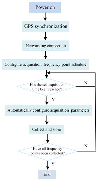
When using the instrument, GNSS synchronization and network connection is the first step. And then configure the acquisition frequency and time table to collect data. The overall workflow of the receiver is shown in Fig. 12.
3.6 Comparison of key instrument indicators
Some of the internationally advanced electromagnetic receivers include the GEOMETRICS EH5 from the United States (Geometrics, 2024), Metronix ADU07 from Germany (Metronix, 2024), Zonge GDP-32II from the United States (Zonge International, 2012), and Phoenix V8 from Canada (Phoenix Geophysics, 2023). Partial parameters of these four instruments are presented in Table 1. From the table, it can be observed that current electromagnetic receivers already cover a wide frequency range. To be more specific, the Metronix ADU07 from Germany is a full-band magnetotelluric instrument, covering frequencies from direct current to radio frequency, enabling various detection methods such as magnetotellurics and controlled-source electromagnetic methods. Additionally, current electromagnetic receivers are moving towards multi-channel synchronous acquisition. All four instruments listed in Table 1 have at least two electric field channels and three magnetic field channels. The German Metronix ADU07 utilizes a combination of high-frequency and low-frequency dual channels, with a total of 10 channels, providing the most detailed electromagnetic data for subsequent data processing. However, the sampling rates of these instruments do not exceed 512 kHz. In terms of storage media, they all use SD cards or other removable flash memory for data storage, and the speed of the storage media may become a bottleneck for high-speed continuous acquisition. The 190 dB dynamic range of the Zonge-GDP-32II likely does not refer to the instantaneous dynamic range but rather to the ratio of the maximum input voltage to the minimum detectable signal when considering the channel gain. According to its manual, the maximum input voltage is ±32 V, while the minimum detectable signal is 0.03 µV, with gain adjustable from 0.125 to 65 536 V/V. In fact, the dynamic range specification of our instrument is determined in the same method, and here the gain is 40 dB.
4.1 Frequency range testing
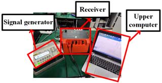
After the development was completed, we conducted system integration testing and performance evaluation (as shown in Fig. 13), including tests on frequency range, background noise, dynamic range, and others.
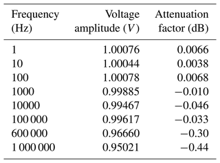
After powering on the prototype, we connected the receiver and signal generator. A sinusoidal wave with a peak-to-peak amplitude of 1 V was applied to the input of the receiver. The test results are summarized in Table 2.
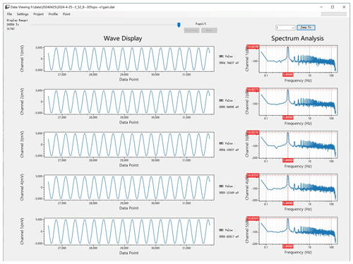
By varying the input signal frequency from 1 Hz to 1 MHz, it was observed that the attenuation factor remained below 3 dB. This indicates that within the frequency range of 1 Hz to 1 MHz, the receiver operates within the −3 dB bandwidth.
4.2 Background noise and dynamic range testing
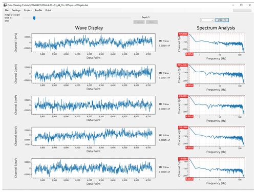
We kept the same connection setup, with the receiver inputting a sine wave with a peak-to-peak amplitude of 1 V. The input signal amplitude was gradually increased until the maximum undistorted sine wave was identified, resulting in a measured value of 3.5 V rms, as depicted in the graph. When the receiver input was shorted, the effective value of the short-circuit noise was measured, yielding a result of 0.25 µV, as shown in Figs. 14 and 15. Based on calculations, the dynamic range was determined to be around 143 dB.
4.3 Transceiver frequency test
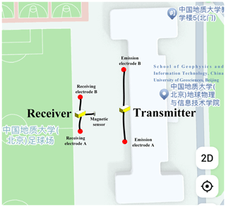
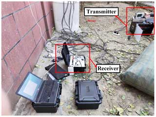
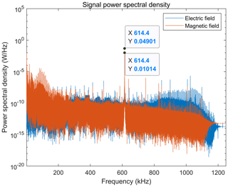
We conducted a joint debugging test of the transmitter and receiver outdoors. A 100 m cable was laid across the campus as shown in Fig. 16, with a distance of 10 m between the transmitting electrodes. Stainless-steel electrodes and induction magnetic sensors were used for reception, with a receiving cable of 50 m and a receiving distance of 10 m. The outdoor test photos are shown in Fig. 17. We use a transmitter to emit a 614.4 kHz square wave, and the receiver collects the spectrum of underground electric and magnetic field data, as shown in Fig. 18. It can be seen that both the electric and magnetic field channels can clearly receive the 614.4 kHz signal, verifying the accuracy of the signal.
In this study, we have developed a novel IoT-based controlled-source ultrasonic audio frequency electromagnetic receiver and provided a comprehensive description of its software and hardware architecture. The system is compatible with both electrical and magnetic measurement techniques, with the receiver capable of sampling up to 2.5 MHz, effectively extending the operating frequency of controllable-source electromagnetic acquisition from the conventional 250 kHz to 1 MHz. This equipment is compact and portable, allowing for easy transportation, and it can instantly store collected data locally or transmit it in real time to higher-level devices such as computers. Furthermore, the system incorporates IoT technology, supporting remote real-time monitoring and control functions, significantly simplifying the complexity of field operations. Through experimental testing, we have validated the integrity of the system data, the efficiency of communication with the upper computer, and other performance indicators, all of which have met the expected design requirements.
Our research is supported by national projects; thus, the data are not publicly accessible due to a confidentiality agreement.
This research was designed, tested, and implemented by all authors. The text was written by ZL. FL and KZ worked on the hardware design. XZ, ZL, and KZ worked on the software design. The other three authors (QZ, HZ, and XW) provided revisions and corrections during the creation of the article and performed the tests.
The contact author has declared that none of the authors has any competing interests.
Publisher’s note: Copernicus Publications remains neutral with regard to jurisdictional claims made in the text, published maps, institutional affiliations, or any other geographical representation in this paper. While Copernicus Publications makes every effort to include appropriate place names, the final responsibility lies with the authors.
We thank the China University of Geosciences (Beijing) for providing an excellent testing environment.
This study is supported by the National Key R&D Program of China (grant nos. 2022YFF0706202 and 2021YFC2801404), the National Natural Science Foundation of China (grant no. 42074155), and the Key Research Program of the Chinese Academy of Sciences (grant no. KGFZD-145-22-06-02).
This paper was edited by Jean Dumoulin and reviewed by Arthur Bouché and one anonymous referee.
Aykaç, S., Timur, E., Sari, C., and Caylak, C.: CSAMT investigations of the Caferbeyli (Manisa/Turkey) geothermal area, J. Earth Syst. Sci., 124, 149–159, 2015. a
Cagniard, L.: Basic theory of the magneto-telluric method of geophysical prospecting, Geophysics, 18, 605–635, 1953. a
Chun-lei, L., Chen-ming, L., Ya-Song, L., Qi-chen, H., and Sheng-wei, C.: Genetic model and exploration target area of geothermal resources in Hongtang Area, Xiamen, China, Journal of Groundwater Science and Engineering, 10, 128–137, 2022. a
Farzamian, M., Alves Ribeiro, J., Khalil, M. A., Monteiro Santos, F. A., Filbandi Kashkouli, M., Bortolozo, C. A., and Mendonça, J. L.: Application of transient electromagnetic and audio-magnetotelluric methods for imaging the monte real aquifer in Portugal, Pure Appl. Geophys., 176, 719–735, 2019. a
Geometrics: Stratagem EH-5-Geometrics: Geometrics, https://www.geometrics.com/product/stratagem-eh5/ (last access: 3 September 2024), 2024. a
Goldstein, M. and Strangway, D.: Audio-frequency magnetotellurics with a grounded electric dipole source, Geophysics, 40, 669–683, 1975. a
Guo, R., Li, M., Yang, F., Xu, S., and Abubakar, A.: Application of supervised descent method for 2D magnetotelluric data inversion, Geophysics, 85, WA53–WA65, 2020. a
Khandelwal, S. and Shreejith, S.: A lightweight multi-attack CAN intrusion detection system on hybrid FPGAs, in: 2022 32nd International Conference on Field-Programmable Logic and Applications (FPL), Hong Kong, China, 5–9 December 2022, IEEE, 425–429, https://doi.org/10.1109/FPL57034.2022.00070, 2022. a
Liu, Y., Wang, G., Guo, X., Hu, J., Wang, J., Wang, X., and Zhao, G.: A Joint Method Based on Geochemistry and Magnetotelluric Sounding for Exploring Geothermal Resources in Sedimentary Basins and Its Application, Water, 14, 3299, https://doi.org/10.3390/w14203299, 2022. a
Metronix: metronixweb, https://www.metronix.de/metronixweb/ (last access: 22 August 2024), 2024. a
Peng, F., Zhao, X., Zhang, S., Duan, H., Du, S., Zhao, Q., and Guo, C.: A portable frequency-domain electromagnetic detection system, Int. J. Circ. Theor. App., 52, 4105–4128, https://doi.org/10.1002/cta.3919, 2024. a
Phoenix Geophysics: Ultra-wideband MT Systems, https://www.phoenixgeophysics.com/ultra-wideband-mt-systems (last access: 2 September 2024), 2023. a
Rong, Z. and Liu, Y.: 3D joint inversion of controlled-source audio-frequency magnetotelluric and magnetotelluric data, Global Geology, 25, 26–33, 2022. a
Sandberg, S. K. and Hohmann, G. W.: Controlled-source audiomagnetotellurics in geothermal exploration, Geophysics, 47, 100–116, 1982. a
Tang, C. and Wang, Z.: Application of High-Frequency Magnetotelluric Method in Exploration of Coal Mine Goaf, Advances in Geosciences, 13, 329–335, 2023. a
Teng, J., Xue, G., and Song, M.: Theory on exploring mineral resources in the second deep space and practices with electromagnetic method, Chinese J. Geophys.-CH, 65, 3975–3985, 2022. a
Wang, H., Liu, J., Guo, W., and Tian, S.: A surface-tunnel frequency domain electromagnetic method for mineral exploration in Tajikistan area, Frontiers in Energy Research, 11, 1247346, https://doi.org/10.3389/fenrg.2023.1247346, 2023. a
Wang, M., Deng, M., Yu, P., Yin, C., Chen, K., and Luo, X.: High-power time-frequency transmission and multi-chain cable multi-component electromagnetic system for deep-water exploration, Chinese J. Geophys.-CH, 65, 3664–3673, 2022. a
Xu, Y., Liu, L., Wu, K., Geng, Z., and Fang, G.: Research on technology of Controlled Source Radio MagnetoTelluric system's transmitter, Journal of Electronics (China), 31, 609–618, 2014. a
Yu, C., Liu, C., Xue, J., Zhang, F., and Li, Y.: Review in the Geophysical Methods for Coalbed Methane Resources in Abandoned Coal Mine, Jilin Daxue Xuebao (Diqiu Kexue Ban)/Journal of Jilin University (Earth Science Edition), 53, 1991–2005, https://doi.org/10.13278/j.cnki.jjuese.20230284, 2023. a
Yuan, Z., Wang, Y., Liu, S., Wang, Y., Zhang, X., Zhao, M., and Zhang, Q.: Research and development of ADS1271 based distributed engineering seismic acquisition unit, in: 2016 Third International Conference on Digital Information Processing, Data Mining, and Wireless Communications (DIPDMWC), Moscow, Russia, 6–8 July 2016, IEEE, 302–306, https://doi.org/10.1109/DIPDMWC.2016.7529407, 2016. a
Zhang, H. and Wang, X.: A new type of photovoltaic monitoring system based on cloud platform, in: Third International Conference on Artificial Intelligence and Electromechanical Automation (AIEA 2022), Changsha, China, 8–10 April 2022, SPIE, Vol. 12329, 623–628, https://doi.org/10.1117/12.2646905, 2022. a
Zhang, K., Lin, N., Wan, X., Yang, J., Wang, X., and Tian, G.: An approach for predicting geothermal reservoirs distribution using wavelet transform and self-organizing neural network: a case study of radon and CSAMT data from Northern Jinan, China, Geomechanics and Geophysics for Geo-Energy and Geo-Resources, 8, 156, https://doi.org/10.1007/s40948-022-00468-1, 2022. a
Zhang, M., Farquharson, C. G., and Liu, C.: Improved controlled source audio-frequency magnetotelluric method apparent resistivity pseudo-sections based on the frequency and frequency–spatial gradients of electromagnetic fields, Geophys. Prospect., 69, 474–490, 2021. a
Zhang, Z., Zhou, F., and Lu, S.: High speed data acquisition system based on AD7760, Instrument Technique and Sensor, 24–26, https://qikan.cqvip.com/Qikan/Article/Detail?id=667598431 (last access: 2 September 2024), 2015. a
Zhou, K., Zhang, Q., Liu, Y., Wu, Z., Lin, Z., Zhao, B., Jiang, X., and Li, P.: Internet-of-things-based four-dimensional high-density electrical instrument for geophysical prospecting, Geosci. Instrum. Method. Data Syst., 10, 141–151, https://doi.org/10.5194/gi-10-141-2021, 2021a. a
Zhou, L., Xie, X., Wang, X., and Yan, L.: Optimal Transceiver Distance of Controlled-source Audio-frequency Magnetotelluric Sounding Method, J. Environ. Eng. Geoph., 26, 111–116, 2021b. a
Zonge International: Gdp-32ii, http://www.zonge.com/legacy/PDF_Equipment/Gdp-32ii.pdf (last access: 22 August 2024), 2012. a
- Abstract
- Introduction
- Basic principles
- Design of IoT-based controlled-source ultrasonic audio frequency electromagnetic receiver
- Instrument testing and result analysis
- Conclusions
- Data availability
- Author contributions
- Competing interests
- Disclaimer
- Acknowledgements
- Financial support
- Review statement
- References


