the Creative Commons Attribution 4.0 License.
the Creative Commons Attribution 4.0 License.
A hydrate reservoir renovation device and its application in nitrogen bubble fracturing
Jingsheng Lu
Yuanxin Yao
Jinhai Yang
Deqing Liang
Yiqun Zhang
Decai Lin
Kunlin Ma
Natural gas hydrate (GH) is a significant potential energy source due to its large reserves, wide distribution, high energy density, and low pollution. However, the gas production rate of past gas hydrate production tests is much lower than the requirement of commercial gas production. Reservoir stimulation technologies like hydraulic fractures provide one potential approach to enhance gas production from GH. The reservoir reformation behavior of the hydrate-bearing sediments (HBSs), particularly sediments with a high clay content, is a complex process during a hydraulic fracturing operation which has been poorly understood and thus hardly predictable. This paper presents an experimental facility that was developed to analyze the hydraulic fracture mechanism in synthesized HBSs. This facility can be used to form GH in sediments, conduct visual observation of hydraulic fracturing experiments, and measure the permeability of HBSs under high-pressure (up to 30 MPa) and low-temperature conditions (from 253.15 to 323.15 K). It is mainly composed of a pressure control and injection unit, a low temperature and cooling unit, a cavitation unit, a visual sapphire reactor, and a data acquisition and measurement unit. The hydraulic fracture module consists of a gas cylinder, fracturing pump, hopper, proppant warehouse, and valves. The sapphire reservoir chamber is applied to observe and measure the fracture of HBSs during hydraulic fracturing. The permeability test module is composed of a constant-flux pump and pressure sensors, which can evaluate the permeability performance before and after the hydraulic fracture in HBSs. The fundamental principles of this apparatus are discussed. Some tests were performed to verify hydraulic fracture tests, and permeability tests could be practically applied in the HBS exploitation.
- Article
(2159 KB) - Full-text XML
- BibTeX
- EndNote
Nature gas hydrate (GH) is an ice-like crystal substance, named fire in ice, which is formed by water and gas under low-temperature and high-pressure conditions (Sloan and Koh, 2007). It is largely stored in the deep-water and permafrost sediments (Boswell, 2009). GH has been considered a potential low-carbon energy source in the 21st century. The methods of the depressurization test (Tang et al., 2007), thermal simulation test (Wang et al., 2014), inhibitor injection test (Tohidi et al., 2015), carbon dioxide replacement test (Boswell et al., 2017), and solid fluidization test (Zhou et al., 2018) are applied to GH production in the past 20 years. However, the production rate of methane in these tests cannot meet the commercial requirement, and the key factor of hydrate commercial production is daily production rates (Chen et al., 2022; Yamamoto et al., 2022). Thus, the stimulation technology of HBSs should be considered to achieve an economically viable gas production rate from GH reservoirs (Wu et al., 2021).
Hydraulic fracturing is one of the useful stimulation technologies that has been widely applied to the “shale gas revolution” in the last 3 decades, which is also investigated to enhance production technology for GH (Terzariol and Santamarina, 2021; Terzariol et al., 2017) (Fig. 1). Few hydraulic fracture studies of HBSs were reported recently (Sun et al., 2019, 2021; Shen et al., 2020; Yao et al., 2021; Zhong et al., 2020; Lv et al., 2021; Konno et al., 2016; Ito et al., 2008; Ma et al., 2022). One challenge is how to detect the fracturing ability and features of HBSs under low-temperature and high-pressure conditions, while the weak cementation, low permeability, and high fine content behavior of HBSs may lead to sand production (Lu et al., 2019), wellbore collapse, and formation instability (Wu et al., 2019; Li et al., 2016; Q. Wu et al., 2023) during the fracturing stimulation operation. Although the innovative experimental apparatus for the sand production (Lu et al., 2018, 2021a), cavitating jet (Zhang et al., 2020), mechanical behavior (Seol et al., 2019; Spangenberg et al., 2020; Li et al., 2019), and kinetics behavior (Masoudi et al., 2019) of HBSs were developed, it is still hard to evaluate the fracturing performance (like fracture generation, growth, and determination) in HBSs. Meanwhile, proppants are widely applied in hydraulic fracture fluids to increase the permeability of unconventional reservoirs (Hafez et al., 2021; Wang et al., 2023a, b). The performance of proppants in HBSs is also a key factor of the stimulation technology. Furthermore, the fractures of HBSs may trigger submarine slope failure and seafloor destabilization during the GH natural dissolution by global warming and marine salinity changes (Hassanpouryouzband et al., 2020). It is significant to study the fracture initiation and propagation mechanism in HBSs and how the fractures respond to the changes in the sedimentary properties and temperature and pressure conditions during hydraulic stimulation and exploitation, as well as the natural dissolution process.
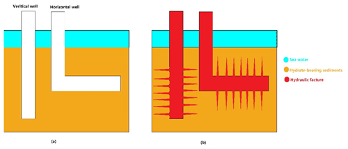
Figure 1Schematic diagrams of (a) hydrate-bearing sediment exploitation in a vertical well and a horizontal well and (b) hydraulic fracture in HBSs.
However, the expensive cost of field tests and restriction of numerical simulation leads to the laboratory hydraulic fracture of HBS being the best option (Tang et al., 2007). To study the ability of stimulation using hydraulic fracture in HBS, a novel experimental apparatus that consists of a set of hydraulic fracture hydrate equipment was designed and developed. It was successfully used to study the ability and feature of the hydraulic fracture in HBS and the coupling effects of multi-field (thermos-hydro-mechanical-phase change) on GH exploitation under reservoir conditions.
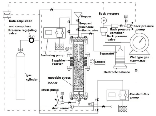
The marine HBS is usually buried in deep water (1200 m) with high compaction stress (10–25 MPa), high pore pressure (10–20 MPa), and low temperature (275.15–288.15 K), so the effect of high crustal stress, high pressure, and low temperature on hydraulic fracture could not be ignored during the stimulation process. Three key factors should be considered in the design, namely (1) the HBS formation, (2) in situ hydraulic fracture tests of HBSs at high pressure and low temperature, and (3) fracture visualization of HBSs under in situ conditions. The schematic configuration of the designed apparatus, which is composed of a pressure control and injection unit, a low temperature and cooling unit, a cavitation unit, a visual sapphire reactor, and a data acquisition and measurement unit, is shown in Fig. 2.
2.1 Pressure and stress control system
In Figs. 3 and 4, the pressure and stress control system consists of the following four modules: the movable stress module (movable stress loader, stress pump, and strain sensor), the hydraulic fracture module, the back-pressure module (back-pressure pump, back-pressure container, and back-pressure valve), and pore pressure module (gas pressure and constant-flux pump). The pressure of the movable stress module, the hydraulic fracture module, the back-pressure module, and the pore pressure module are provided by the stress pump (30 MPa), constant-flux pump (30 MPa), fracturing pump (30 MPa), back-pressure pump (10 MPa), and methane gas (13 MPa), respectively. The automatic pressure relief valve is fixed to avoid pressure over the system limit. The strain sensor is assembled on a movable stress loader to measure the axial deformation (subsidence).
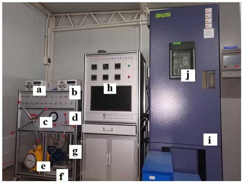
Figure 3The front view of the apparatus: (a) fracturing pump, (b) pore pressure pump, (c) overlying stress, (d) back-pressure pump, (e) wet-type gas flowmeter, (f) electronic balance, (g) separator, (h) control cabinet and computer, (i) air bath, and (j) visual window of air bath and sapphire reactor.
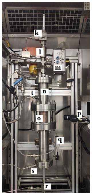
Figure 4The inside view of the air bath: (k) Hopper valve, (l) proppant warehouse, (m) electric valve of proppant warehouse, (n) up chamber of the sapphire reactor, (o) sapphire window of the sapphire reactor, (p) camera, (q) strain sensor, (r) pore pressure valve and safety valve, (s) stress valve, and (t) temperature sensor.
2.2 Low temperature and air cooling system
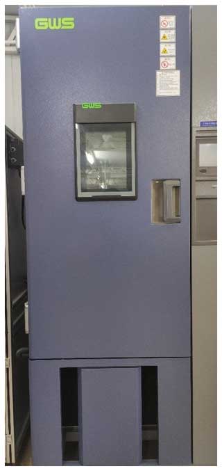
To control the temperature in the reactor, the programmable air bath is applied (Fig. 5). The programmable air bath is manufactured by Guangzhou–GWS Environmental Equipment Co., Ltd, which can provide a temperature range from 253.15 to 323.15 K, and the accuracy is ±0.5 K.
The programmable air bath applied the 380 V voltage for cooling power. The visual window and inside light of the programmable air bath are applied to the visual reactor by human eye and camera. There is a temperature sensor (PT-100; the accuracy is ±0.1 K) arranged in the middle of the reactor (Fig. 4) which can collect the reactor temperature in real time.
2.3 Hydraulic fracture, permeability test, and production system
The hydraulic fracture module consists of the gas cylinder, fracturing pump, hopper, proppants warehouse, and valves. After adding the proppants into the warehouse through the hopper, the hydraulic fracture pressure increased with colored water (fracturing fluid) and N2 gas by the fracturing pump and gas cylinder, respectively. The high-pressure hydraulic fracturing fluid with proppants flows directly through the pipe (diameter ⊘ = 8 mm) into the visual sapphire reactor when the electric valve of the proppants warehouse opens.
The permeability test module is composed of the constant-flux pump and pressure sensors. It determines the permeability of HBSs before and after hydraulic fracturing through Darcy's law (P. Wu et al., 2023; Lu et al., 2021b).
The production module is constituted of a back-pressure module, separator, electronic balance, and gas flowmeter. It is applied to test the production capacity of HBSs after the hydraulic fracture.
2.4 Visual sapphire reactor
The visual sapphire reactor (Fig. 4) is divided into three parts of the up chamber (Φ = 40 mm × 140 mm; 125 mL), visual window chamber, and down chamber (Φ = 40 mm × 200 mm; 250 mL). The body material of the up and down chambers is stainless steel (316 L) with an O-ring seal which can tolerate 20 MPa. The sapphire hollow cylinder (Φ = 40 mm × 60 mm; 75 mL) is applied to the visual window chamber for human eye and camera monitoring.
2.5 Data acquisition and measurement control system
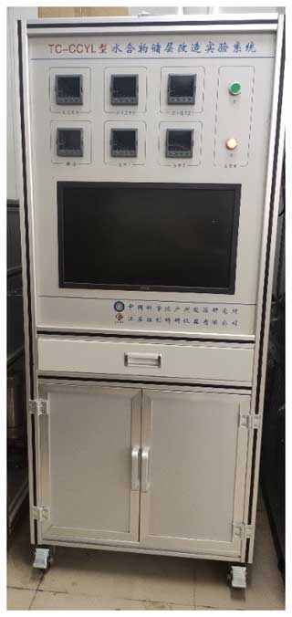
The digital acquisition and control card are applied to ensure real-time data acquisition by Moxa C168H. Through the control cabinet (Fig. 6), the hydrate fracturing pressure, pore injection pressure (bottom pressure), pore pressure (up pressure), production pressure (up pressure), temperature, and movable stress can be displayed and collected. The gas measuring equipment is the BSD05 wet flow meter for gas monitoring (measuring range 12.5 L min−1; ±1 %) by Krom Co., Ltd. The pressure sensor is manufactured by Trafag AG with a range of 30 MPa and an accuracy of 0.1 % full scale.
The experimental process and the related control parameters of equipment are controlled by Visual Basic (VB)-compiled experiment measurement control software. The data of real-time acquisition are from the reactor chamber internal pressure, production pressure, injection pressure, movable pressure, and other parameters. The experimental data can be output in Microsoft Excel form. The software can set and control the electric valve.
3.1 Hydrate formation
The specific experimental process is as follows:
-
Sample formation. First, the hole of the hydraulic jet pipe is coated with a thin filter paper which is used to prevent sand from entering the hydraulic jet pipe. Then sediments with a certain moisture content are put into the reactor. For the compaction of the sediment sample, 1 MPa stress is applied by the movable stress loader for 1 min. After vacuuming the system for 5 min, methane gas was injected into the reactor with a stress loader (effective stress of no more than 1 MPa). Finally, the pore pressure and stress reached equilibrium at 10 and 11 MPa, respectively. After settling down at 293.15 K for 24 h (methane, water, and sediments fully mixed), the temperature of the reactor was cooled to 274.15 K. The pressure in the reactor was gradually balanced at about 72 to 144 h, while the hydrate synthesis process in the sample was fully completed by gas consumption. Here, the hydrate saturation was calculated by the Soave–Redlich–Kwong (SRK) equation.
-
Permeability test of hydrate-bearing sediment before fracturing. The pre-cooled water was injected into the hydrate-bearing sediment from bottom to top. The free methane was released from the top and substituted by pre-cooled water. Then the constant pressure difference between the two ends of the reactor was constantly adjusted to conduct the liquid seepage experiment. When the discharge rate is stable in the flowmeter, the average flow rate is applied to calculate the sediment–water permeability.
-
Hydraulic fracturing test. The proppants were added from the hopper to the proppant warehouse. After the permeability test and water displacement, the fracturing fluid with red color was pumped into the proppant warehouse by the fracturing pump and mixed with the proppants above the pore pressure (about 1 MPa). When the electric valve opened, the fracturing fluid and proppant mixture entered through the hydraulic jet pipe, broke through the thin filter paper, and fractured the HBSs. A camera recorded the fracturing process in front of the sapphire cylinder.
-
Permeability test of hydrate-bearing sediments after fracturing. The permeability test is conducted after fracturing as point (1) tests.
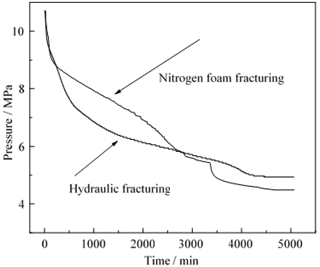
The experimental tests are shown in Table 1. Figure 7 shows the pressure and temperature changes during the hydrate formation process in the test. Different volumes of deionized water were added to dry sand for different hydrate saturation. The hydrate saturation was calculated by gas pressure drop via the SRK equation. The hydrate saturation of the two tests is 39.7 % and 42.2 %, respectively. Two different fracturing methods, namely the nitrogen foam fracturing group and hydraulic fracturing group, are applied.
3.2 Hydraulic fracture test in hydrate-bearing sediments
After hydraulic fracturing in Test 1, no more obvious ductile fractures were photographed around the sapphire reservoir. Therefore, the pressure changed a little but did not significantly climb during hydraulic fracturing.
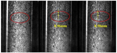
In Test 2, the gas fracturing group can supply a high enough pressure in the fracturing fluid to fracture the HBSs at a guaranteed flow rate. As shown in Fig. 8, the fracture opening and closing can be seen from the sapphire windows. The expansion of fracture is from 0 to 0.96 mm and then reduced from 0.96 to 0.58 mm in 1 min. Figure 9 shows the changes in pressure and temperature in the reactor before and after fracturing. The fracture pressure of the HBSs at this point is 14.42 MPa, and the extension pressure of the fracture reached 9.54 MPa. Figure 10 shows the changes in axial stress and sediment subsidence before and after the instant of fracturing. The axial stress and subsidence of HBSs increase to 0.51 MPa and 0.53 mm, respectively. Then the subsidence of HBSs retreats to 0.38 mm, which corresponds to fracture closure in Fig. 8.
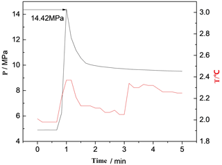
Figure 9Nitrogen foam fracturing group before and after fracturing instantaneous pressure and temperature changes.
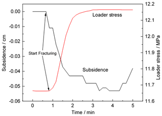
Figure 10Nitrogen foam fracturing group before and after fracturing instantaneous axial compression and sediment deposition.
The hydraulic fracturing experiments verified the fracture ability of HBSs.
3.3 Permeability test in hydrate-bearing sediments
The permeability of hydrate-bearing sediments are tested by Darcy's law. The permeability K is calculated from the flow rate q, cross-sectional area A, pressure differential ΔP, viscosity μ, and the space coordinate in the flow direction L. The inject pressure P1 and flow rate q are pumped water by the constant-flux pump, while the outlet pressure P2 is measured. The pressure differential ΔP will decrease after the operation of hydraulic fracture, so the permeability K will increase in HBSs.
The design purpose of this apparatus is to study the hydraulic fracture mechanism of hydrate exploitation and provide support for the application of reservoir reformation technology in GH reservoirs. Two pilot experiments were conducted using liquid and gas hydraulic fluids, respectively, to investigate the applicability of this system.
According to previous experience, this apparatus creatively developed a visualization test platform of hydraulic fracture in HBSs with the function of movable stress, in situ GH synthesis, and deformation monitoring. The apparatus can carry out the in situ synthesis of HBSs and the tests of reservoir reformation experiments during HBS exploitation in the same environment and provide the visual fracturing and reservoir deformation monitor. Through the pilot experiment in the early stage, the basic physical parameters of HBS fracture were collected, and the experimental steps of in situ hydrate synthesis and fracturing in the HBSs were verified.
Furthermore, this apparatus also had well commonality and flexibility. A series of visual experiments with low temperature and high pressure, such as water jetting in HBSs and CO2 hydrate geology sequestration-related experiments, are planned soon. This facility is also applied to CO2 geology sequestrated in the saline aquifer which can provide visuals of the saline aquifer during the CO2 injection and sequestration.
The data that support the findings of this study are available from the corresponding author upon reasonable request.
JL: writing – original draft; writing – review and editing. YY: data curation; visualization. DoL: conceptualization; funding acquisition; supervision, writing – review and editing. JY: conceptualization; writing – review and editing. AL: conceptualization; writing – review and editing. DeqL: conceptualization; supervision. YZ: investigation; resources; visualization. DecL and KM: visualization.
The contact author has declared that none of the authors has any competing interests.
Publisher's note: Copernicus Publications remains neutral with regard to jurisdictional claims made in the text, published maps, institutional affiliations, or any other geographical representation in this paper. While Copernicus Publications makes every effort to include appropriate place names, the final responsibility lies with the authors.
This work has been supported by the Science and Technology Planning Project of Guangdong Province (grant no. 2021A0505030053), Science and Technology Projects in Key Areas of Nansha District (grant no. 2023ZD017), Natural Science Foundation of China (grant nos. 52004261, 52174009, 5161101020, and 51976227), Guangzhou Science and Technology Planning Project (grant no. 202201010591), Guangdong Major Project of Basic and Applied Basic Research (grant no. 2020B0301030003), special project for Marine Economy Development of Guangdong Province (grant no. GDNRC[2022]43), Guangdong Special Support Program (grant no. 2019BT02L278), NSFC/RGC Joint Research Scheme sponsored by the National Natural Science Foundation of China, Research Grants Council of Hong Kong (project No. n_PolyU518/16), and China Scholarship Council (grant no. 202104910253).
This paper was edited by Antonio Annis and reviewed by three anonymous referees.
Boswell, R.: Is Gas Hydrate Energy Within Reach?, Science, 325, 957–958, 2009.
Boswell, R., Schoderbek, D., Collett, T. S., Ohtsuki, S., White, M., and Anderson, B. J.: The Ignik Sikumi field experiment, Alaska North Slope: Design, operations, and implications for CO2–CH4 exchange in gas hydrate reservoirs, Energy Fuels, 31, 140–153, https://doi.org/10.1021/acs.energyfuels.6b01909, 2017.
Chen, X., Lu, H., Gu, L., Shang, S., Zhang, Y., Huang, X., and Zhang, L.: Preliminary evaluation of the economic potential of the technologies for gas hydrate exploitation, Energy, 243, 123007, https://doi.org/10.1016/j.energy.2021.123007, 2022.
Hafez, A., Liu, Q., Finkbeiner, T., Alouhali, R. A., Moellendick, T. E., and Santamarina, J. C.: The effect of particle shape on discharge and clogging, Sci. Rep., 11, 1–11, https://doi.org/10.1038/s41598-021-82744-w, 2021.
Hassanpouryouzband, A., Joonaki, E., Vasheghani Farahani, M., Takeya, S., Ruppel, C., Yang, J., English, N. J., Schicks, J. M., Edlmann, K., Mehrabian, H., Aman, Z. M., and Tohidi, B.: Gas hydrates in sustainable chemistry, Chem. Soc. Rev., 49, 5225–5309, https://doi.org/10.1039/c8cs00989a, 2020.
Ito, T., Igarashi, A., Suzuki, K., Nagakubo, S., Matsuzawa, M., and Yamamoto, K.: Laboratory study of hydraulic fracturing behavior in unconsolidated sands for methane hydrate production, Offshore Technol. Conf. Proc., 2, 969–975, https://doi.org/10.2118/19324-ms, 2008.
Konno, Y., Jin, Y., Yoneda, J., Uchiumi, T., Shinjou, K., and Nagao, J.: Hydraulic fracturing in methane-hydrate-bearing sand, RSC Adv., 6, 73148–73155, https://doi.org/10.1039/c6ra15520k, 2016.
Li, Y., Liu, W., Zhu, Y., Chen, Y., Song, Y., and Li, Q.: Mechanical behaviors of permafrost-associated methane hydrate-bearing sediments under different mining methods, Appl. Energy, 162, 1627–1632, https://doi.org/10.1016/j.apenergy.2015.04.065, 2016.
Li, Y., Wu, P., Liu, W., Sun, X., Cui, Z., and Song, Y.: A microfocus x-ray computed tomography based gas hydrate triaxial testing apparatus, Rev. Sci. Instrum., 90, 055106, https://doi.org/10.1063/1.5095812, 2019.
Lu, J., Xiong, Y., Li, D., Shen, X., Wu, Q., and Liang, D.: Experimental investigation of characteristics of sand production in wellbore during hydrate exploitation by the depressurization method, Energies, 11, 1673, https://doi.org/10.3390/en11071673, 2018.
Lu, J., Xiong, Y., Li, D., Liang, D., Jin, G., He, Y., and Shen, X.: Experimental study on sand production and sea bottom subsidence of non-diagenetic hydrate reservoirs in depressurization production, Mar. Geol. Quatern. Geol., 39, 142–154, https://doi.org/10.16562/j.cnki.0256-1492.2019012301, 2019.
Lu, J., Li, D., Liang, D., Shi, L., Zhou, X., and He, Y.: An innovative experimental apparatus for the analysis of sand production during natural gas hydrate exploitation, Rev. Sci. Instrum., 92, 105110, https://doi.org/10.1063/5.0065760, 2021a.
Lu, J., Li, D., Liang, D., Shi, L., He, Y., and Xiong, Y.: Experimental research on the dynamic permeability of hydrate silty-clay reservoirs during water driven and exploitation, J. Nat. Gas Sci. Eng., 94, 104071, https://doi.org/10.1016/j.jngse.2021.104071, 2021b.
Lv, T., Cai, J., Ding, Y., Pan, J., Chen, Z., and Li, X.: Numerical Evaluation of Long-Term Depressurization Production of a Multilayer Gas Hydrate Reservoir and Its Hydraulic Fracturing Applications, Energy Fuels, 36, 3154–3168, https://doi.org/10.1021/acs.energyfuels.1c04017, 2021.
Ma, X., Jiang, D., Sun, Y., and Li, S.: Experimental study on hydraulic fracturing behavior of frozen clayey silt and hydrate-bearing clayey silt, Fuel, 322, 124366, https://doi.org/10.1016/j.fuel.2022.124366, 2022.
Masoudi, A., Jafari, P., Nazari, M., Kashyap, V., Eslami, B., Irajizad, P., and Ghasemi, H.: An in situ method on kinetics of gas hydrates, Rev. Sci. Instrum., 90, 035111, https://doi.org/10.1063/1.5082333, 2019.
Seol, Y., Lei, L., Choi, J. H., Jarvis, K., and Hill, D.: Integration of triaxial testing and pore-scale visualization of methane hydrate bearing sediments, Rev. Sci. Instrum., 90, 235606, https://doi.org/10.1063/1.5125445, 2019.
Shen, S., Li, Y., Sun, X., Wang, L., and Song, Y.: Experimental study on the permeability of methane hydrate-bearing sediments during triaxial loading, J. Nat. Gas Sci. Eng., 82, 103510, https://doi.org/10.1016/j.jngse.2020.103510, 2020.
Sloan Jr., E. D. and Koh, C. A.: Clathrate Hydrates of Natural Gases, CRC Press, 1–10, https://doi.org/10.1201/9781420008494, 2007.
Spangenberg, E., Heeschen, K. U., Giese, R., and Schicks, J. M.: “Ester” – A new ring-shear-apparatus for hydrate-bearing sediments, Rev. Sci. Instrum., 91, 064503, https://doi.org/10.1063/1.5138696, 2020.
Sun, J., Ning, F., Liu, T., Liu, C., Chen, Q., Li, Y., Cao, X., Mao, P., Zhang, L., and Jiang, G.: Gas production from a silty hydrate reservoir in the South China Sea using hydraulic fracturing: A numerical simulation, Energy Sci. Eng., 7, 1106–1122, https://doi.org/10.1002/ese3.353, 2019.
Sun, Y., Li, S., Lu, C., Liu, S., Chen, W., and Li, X.: The characteristics and its implications of hydraulic fracturing in hydrate-bearing clayey silt, J. Nat. Gas Sci. Eng., 95, 104189, https://doi.org/10.1016/j.jngse.2021.104189, 2021.
Tang, L. G., Li, X. Sen, Feng, Z. P., Li, G., and Fan, S. S.: Control mechanisms for gas hydrate production by depressurization in different scale hydrate reservoirs, Energy Fuels, 21, 227–233, https://doi.org/10.1021/ef0601869, 2007.
Terzariol, M. and Santamarina, J. C.: Multi-well strategy for gas production by depressurization from methane hydrate-bearing sediments, Energy, 220, 1–8, https://doi.org/10.1016/j.energy.2020.119710, 2021.
Terzariol, M., Goldsztein, G., and Santamarina, J. C.: Maximum recoverable gas from hydrate bearing sediments by depressurization, Energy, 141, 1622–1628, https://doi.org/10.1016/j.energy.2017.11.076, 2017.
Tohidi, B., Anderson, R., Mozaffar, H., and Tohidi, F.: The Return of Kinetic Hydrate Inhibitors, Energy Fuels, 29, 8254–8260, https://doi.org/10.1021/acs.energyfuels.5b01794, 2015.
Wang, H., Wu, P., Li, Y., Liu, W., Pan, X., Li, Q., He, Y., and Song, Y.: Gas permeability variation during methane hydrate dissociation by depressurization in marine sediments, Energy, 263, 125749, https://doi.org/10.1016/j.energy.2022.125749, 2023a.
Wang, H., Liu, W., Wu, P., Pan, X., You, Z., Lu, J., and Li, Y.: Gas recovery from marine hydrate reservoir: Experimental investigation on gas flow patterns considering pressure effect, Energy, 275, 127482, https://doi.org/10.1016/j.energy.2023.127482, 2023b.
Wang, Y., Li, X. Sen, Li, G., Huang, N. S., and Feng, J. C.: Experimental study on the hydrate dissociation in porous media by five-spot thermal huff and puff method, Fuel, 117, 688–696, https://doi.org/10.1016/j.fuel.2013.09.088, 2014.
Wu, N., Li, Y., Wan, Y., Sun, J., Huang, L., and Mao, P.: Prospect of marine natural gas hydrate stimulation theory and technology system, Nat. Gas Ind. B, 8, 173–187, https://doi.org/10.1016/j.ngib.2020.08.003, 2021.
Wu, P., Li, Y., Yu, T., Wu, Z., Huang, L., Wang, H., and Song, Y.: Microstructure evolution and dynamic permeability anisotropy during hydrate dissociation in sediment under stress state, Energy, 263, 1–10, https://doi.org/10.1016/j.energy.2022.126126, 2023.
Wu, Q., Dou, X., Zhao, Y., Liu, Z., and Li, Y.: Discrete element simulation of the hydrate-bearing sediments mechanical behaviors under typical hydrate dissociation patterns, Gas Sci. Eng., 115, 205020, https://doi.org/10.1016/j.jgsce.2023.205020, 2023.
Wu, Y., Li, N., Hyodo, M., Gu, M., Cui, J., and Spencer, B. F.: Modeling the mechanical response of gas hydrate reservoirs in triaxial stress space, Int. J. Hydrog. Energ., 44, 26698–26710, https://doi.org/10.1016/j.ijhydene.2019.08.119, 2019.
Yamamoto, K., Boswell, R., Collett, T. S., Dallimore, S. R., and Lu, H.: Review of Past Gas Production Attempts from Subsurface Gas Hydrate Deposits and Necessity of Long-Term Production Testing, Energy Fuels, 36, 5047–5062, https://doi.org/10.1021/acs.energyfuels.1c04119, 2022.
Yao, Y., Guo, Z., Zeng, J., Li, D., Lu, J., Liang, D., and Jiang, M.: Discrete Element Analysis of Hydraulic Fracturing of Methane Hydrate-Bearing Sediments, Energy Fuels, 35, 6644–6657, https://doi.org/10.1021/acs.energyfuels.1c00248, 2021.
Zhang, Y., Zhao, K., Wu, X., Tian, S., Shi, H., Wang, W., and Zhang, P.: An innovative experimental apparatus for the analysis of natural gas hydrate erosion process using cavitating jet, Rev. Sci. Instrum., 91, 095107, https://doi.org/10.1063/5.0011951, 2020.
Zhong, X., Pan, D., Zhai, L., Zhu, Y., Zhang, H., Zhang, Y., Wang, Y., Li, X., and Chen, C.: Evaluation of the gas production enhancement effect of hydraulic fracturing on combining depressurization with thermal stimulation from challenging ocean hydrate reservoirs, J. Nat. Gas Sci. Eng., 83, 103621, https://doi.org/10.1016/j.jngse.2020.103621, 2020.
Zhou, S., Li, Q., Wei, C., Zhou, J., Pang, W., Yufa, H., Xin, L., Xu, L., Qiang, F., and Jiang, L.: The world's first successful implementation of solid fluidization well testing and production for non-diagenetic natural gas hydrate buried in shallow layer in deep water, Proc. Annu. Offshore Technol. Conf., 4, 2784–2794, https://doi.org/10.4043/28759-ms, 2018.


