the Creative Commons Attribution 4.0 License.
the Creative Commons Attribution 4.0 License.
 | 29 Apr 2024
Research and application of a flexible measuring array for deep displacement of landslides
Yang Li
Zhong Li
Qifeng Guo
Yimin Liu
Daji Zhang
The multidimensional and multi-sliding surface measurement of deep-seated displacement on landslides poses a significant technical challenge in landslide monitoring and early warning. The fixed-borehole inclinometer serves as an important measurement method based on drilling for this purpose. In this study, a novel flexible measurement array for deep-seated landslide displacement and its installation and measurement processes were developed, enabling higher accuracy in full-hole multidimensional deformation measurement. The measurement array consists of individual measurement probes as basic units, connected in series through coaxial cables and high-pressure rubber hoses, forming a flexible measurement array. Each probe is equipped with acceleration and magnetic field sensors, allowing for the measurement of borehole inclination and azimuth angles and providing a more comprehensive understanding of the deformation of deep-seated landslides. This flexible measurement array resolves the limitations of traditional fixed inclinometers, such as limited probe quantity or inaccurate installation positions that fail to reflect the deformation trend of the landslide body. Moreover, it eliminates the need for auxiliary installation accessories like pulleys and inclinometer pipes, simplifying the mechanical structure and installation process, which represents an advancement in methodology and an improvement in measurement techniques. This array provides a more comprehensive and improved monitoring tool for disaster prevention and mitigation, thereby enhancing the level of geological hazard monitoring and early warning technology.
- Article
(1939 KB) - Full-text XML
- BibTeX
- EndNote


China is a vast country with a complex geological structure, which is also characterized by its mountainous terrain, with mountainous areas accounting for approximately two-thirds of the total land area (Li et al., 2004; Liu et al., 2022). Within these mountainous regions, the primary manifestations of natural disasters are landslides and slope failures. Due to their unique characteristics and sudden occurrence, landslides and slope failures often result in significant losses to the natural environment, human lives, and properties, as well as engineering infrastructure (Liu, 2012).
In China, for instance, an annual report (China Institute of Geo-Environment Monitoring, 2022) shows that types of geological disasters in 2022 included 3919 landslides, 1366 collapses, 202 debris flows, 153 ground subsidences, 4 ground fissures, and 15 ground subsidences. A total of 90 people were killed, 16 were missing, and 34 were injured, causing direct economic losses of CNY 1.5 billion.
Therefore, the general monitoring method for mountain landslide and collapse involves placing measuring instruments or equipment for landslides and collapses at the field site and its surrounding area and conducting continuous or periodic measurements (Zhou, 2004). The purpose of achieving measurements of landslides, collapses, and other phenomena through field automation monitoring is to accurately determine the planar coordinates, elevation, or three-dimensional relative displacement values of the monitoring network and deformation monitoring points. By employing appropriate data processing, dynamic data such as horizontal displacement, vertical displacement, and relative displacement of cracks and sliding zones are provided for the monitoring network and deformation monitoring points. These data serve the purpose of understanding the deformation patterns of landslides, predicting hazards, evaluating disaster prevention and control measures, and providing support for relevant departments and government decision-making (Stark et al., 2005; Yin and Wu, 2012; Li et al., 2016).
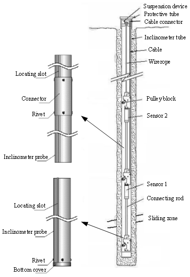
In terms of methods for monitoring deep-seated landslide displacement, the mainstream approaches both domestically and internationally primarily involve the use of automatic or fixed-borehole inclinometers (Stark and Choi, 2008; Li et al., 2015; Giuseppe et al., 2020). These methods employ inclinometers installed in boreholes to monitor the sliding locations of deep-seated landslide bodies, capturing the horizontal displacement, sliding velocity, and intermittent sliding of the landslide (Sarolkar et al., 2022). The deformation of deep-seated relative displacement precedes surface displacement, and the two are closely related. Monitoring the deformation of deep-seated relative displacement enables early prediction of landslide stability. The schematic diagram of the measurement is shown in Fig. 1.
In academia, extensive research and practical work have been conducted by domestic and international scholars on the design of borehole inclinometers for measuring deep-seated landslide displacement. As early as 1992, the University of British Columbia (UBC) developed a prototype inclinometer that employs a three-component fluxgate magnetometer to obtain a compass bearing, presented a unified theory of data interpretation that can be applied to all inclinometers, and discussed the application of the theory to the UBC inclinometer (Erik and Garry, 1992). Zhou et al. (2013) developed a deep-seated landslide displacement monitoring instrument that measures torsional orientation. The instrument utilizes triaxial accelerometers and magnetoresistive sensors to track and monitor the entire sliding process of landslides. Real-time data transmission is achieved through GPRS technology. Giuseppe et al. (2020) presented a low-cost multi-module fixed inclinometer for continuous landslide monitoring. The displacement measurement accuracy of the inclinometer can reach 0.37 % of its total length, and linear testing demonstrated a high linearity within a tilt angle range of ±20°. Vassallo et al. (2020) demonstrated long-term displacement monitoring using a fixed inclinometer and GPS integrated system, comparing the results with PS-InSAR data to explore the relationship between deep-seated and surface displacements of landslides.
Based on a literature review and practical experience, several limitations of using borehole inclinometers for monitoring deep-seated landslide displacement can be identified.
-
Limited monitoring range. Traditional borehole inclinometers, due to their limited number of probes or inaccurate installation positions, typically only capture localized displacement changes within the borehole, resulting in a relatively small monitoring range. It may be challenging to comprehensively and accurately monitor large-scale landslides or internal displacement within landslide bodies.
-
Complex installation process. Traditional fixed-borehole inclinometers require the assistance of inclinometer pipes for measurements. The inclinometer pipes are fixed and installed inside the landslide body, often utilizing pulleys designed on the inclinometer to position the probe by rolling in the positioning groove of the inclinometer pipe. This process demands high precision during the connection of the positioning groove, significantly increasing the difficulty of instrument installation.
-
Insufficiency in azimuth measurement. Inevitably, inclinometer pipes introduce a torsional angle during the connection process. Traditional inclinometers can only measure the inclination angle but not the torsional angle, leading to measurement errors.
In conclusion, although borehole inclinometers have certain application value in monitoring deep-seated landslide displacement, their limitations in terms of monitoring range, complex installation process, susceptibility to interference, and difficulty in obtaining azimuth angle data necessitate upgrades and improvements to better meet the requirements of geological hazard monitoring and early warning technology.
2.1 System composition
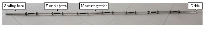
The flexible measurement array for deep-seated landslide displacement consists of individual measurement probes as the basic units, connected to each other through cables and high-pressure rubber hoses (as shown in Fig. 2). The high-pressure rubber hoses ensure a significant degree of flexibility and bending capability between the probes, allowing for a better match to the deformation of the borehole. The instrument cables of the nodes pass through hollow rubber hoses, maintaining a single cable connection from start to finish. The nodes can be connected in series as needed to meet different measurement requirements at various depths. From an external perspective, it appears as a cable line connected to a long string of probes. The four-core cable consists of power supply lines and a 485 bus. The internal probes are all connected to the 485 bus for data transmission. Each probe is equipped with a three-axis accelerometer module and a geomagnetic module, connected to an STM32 series microcontroller through the SPI bus. The data acquisition host controls the STM32 microcontroller via the 485 bus to simultaneously collect incline and azimuth angle data.
This instrument serves as a flexible inclinometer array capable of obtaining full-hole incline data from the bottom to the top of the borehole. It can be customized according to the depth of the borehole to achieve a perfect match. With acceleration and magnetic field sensors installed in each probe, the incline angle and direction of the borehole can be measured, allowing users to gain a more comprehensive understanding of the deformation of deep-seated landslide displacement. At present, the instrument can carry up to 32 measurement probes. Under deep-hole conditions, the full-hole inclinometer can be adapted to deep-hole conditions by modifying the program, thereby modifying the acquisition logic and communication protocol structure. However, if only the number of measurement probes is increased, the overall measurement cost will become very high. Therefore, in engineering applications, the method of increasing the length of flexible joints will dilute the probe density in fixed hole depths to reduce system application costs.
2.2 Technical parameters
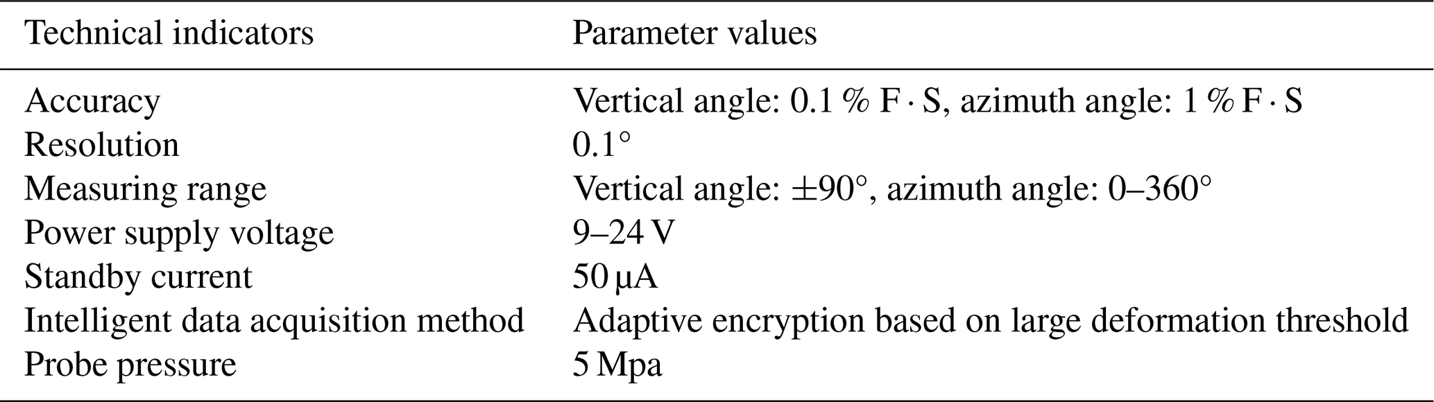
The main technical parameters of the flexible measurement array for deep-seated landslide displacement are shown in Table 1.
The duration of each data acquisition and network transmission of the instrument is about 2 min, and the working current is about 200 mA. The rest of the time is in a dormant state. Working every day consumes approximately 0.33 A h of electricity. The power supply of the full-hole inclinometer comes from a lead–acid battery located on the ground of the orifice. Considering the extreme situation where lead–acid batteries cannot be recharged after a continuous rainy month, using a 20 A h lead–acid battery can ensure the redundant power consumption design of the system.
During each acquisition process, the full-hole inclinometer can perform edge calculation and compare the current acquisition value with the previous acquisition value. If the collected values do not change or fluctuate within a certain range, the full-hole inclinometer can continue to collect and sleep at the predetermined collection frequency. If the collected value exceeds the range of variation, the full-hole inclinometer will immediately carry out repeated collection. If it is determined that the collected value exceeds the limit, the full-hole inclinometer will not sleep and will continue to collect and transmit until three consecutive data points are stable before entering sleep. As a result, the system has implemented adaptive encryption collection logic.
3.1 Principle of deep displacement measurement
Based on the structural characteristics of the flexible measurement array described in Sect. 2, the measurement principle of deep-seated displacement is illustrated in Fig. 3, as mentioned in the previous section.
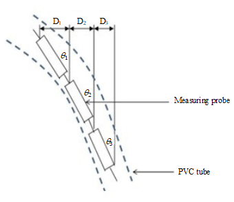
As shown in Fig. 3, the full-hole inclinometer measures the angle θi between the inclinometer casing and the vertical line at each section along the PVC pipe using the inclinometer spacing L. The horizontal displacement di at different elevations is then calculated using Eq. (1).
By incrementally summing from the bottom measurement point of the inclinometer pipe, the actual horizontal displacement, denoted as bi, at any elevation can be obtained, as shown in Eq. (2).
The accumulated horizontal displacement at the mouth of the inclinometer pipe is denoted as B.
Based on the angle and direction data obtained from each probe, the variation of horizontal displacement at different depths along the axis of the inclinometer pipe can be determined. In the above equation, di represents the horizontal displacement of the measurement section; L denotes the segmented length of the measurement point, which is the instrument spacing; θi represents the angle between the inclinometer pipe and the vertical line for the measurement section; bi represents the horizontal displacement of the ith measurement point starting from the bottom of the hole; B represents the horizontal displacement at the mouth of the current measurement pipe; and n represents the number of segments for the monitoring hole, where and H is the depth of the hole.
3.2 Calculation of crown footing and azimuth angles
The flexible inclinometer sensor adopts a triaxial accelerometer and a triaxial magnetic sensor, forming a dual triaxial () system. The axes of the accelerometer and magnetic sensor are parallel, with the z axis pointing downward along the instrument axis, while the x and y axes lie in the plane perpendicular to the instrument axis. The coordinate system for top-foot measurement is illustrated in Fig. 4.
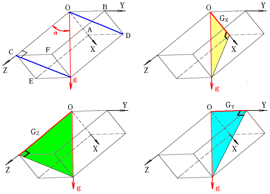
By using the components of gravity acceleration g sensed by the accelerometer and the components of the magnetic field sensed by the magnetic sensor, the values of borehole inclination and azimuth angles at the instrument's location can be calculated according to Eqs. (3) and (4) (Liu, 2016).
In the equations, ax is the output value of the x-axis accelerometer, ay is the output value of the y-axis accelerometer, az is the output value of the z-axis accelerometer, Hx is the magnetic flux gate (or magnetic resistance) output value along the x axis, Hy is the magnetic flux gate (or magnetic resistance) output value along the y axis, Hz is the magnetic flux gate (or magnetic resistance) output value along the z axis, and g is the value of gravitational acceleration .
The installation process of the measurement array mainly involves procedures such as indoor installation, adjustment, performance testing, and assembly.
4.1 Sensor deployment
-
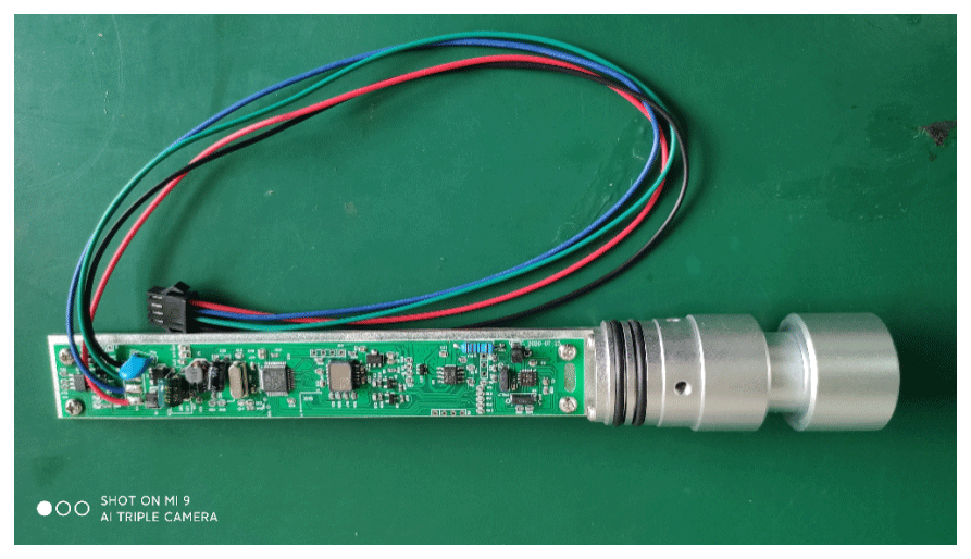
Prepare the installation equipment, including tools, sensors, sensor mounting plates, flexible connectors, pressure-resistant outer pipes, sealing rings, connecting wires, and non-magnetic screws, required for sensor installation (see Fig. 5).
-
Stepwise installation of sensors
Place the sealing ring on the connector, then attach the sensor mounting plate to the connector and secure the sensors to the mounting plate using screws. Finally, solder the four connecting wires (see Fig. 6).

4.2 Sensor calibration
The sensors can be assembled into the configuration shown in Fig. 7 for sensor calibration. As shown in Fig. 8, the sensors are then clamped onto the HZT-60 inclinometer calibration table (Li et al., 2015), and calibration is performed for zenith angles and azimuth angles at 16 different positions.
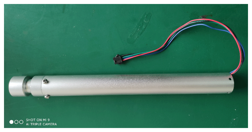

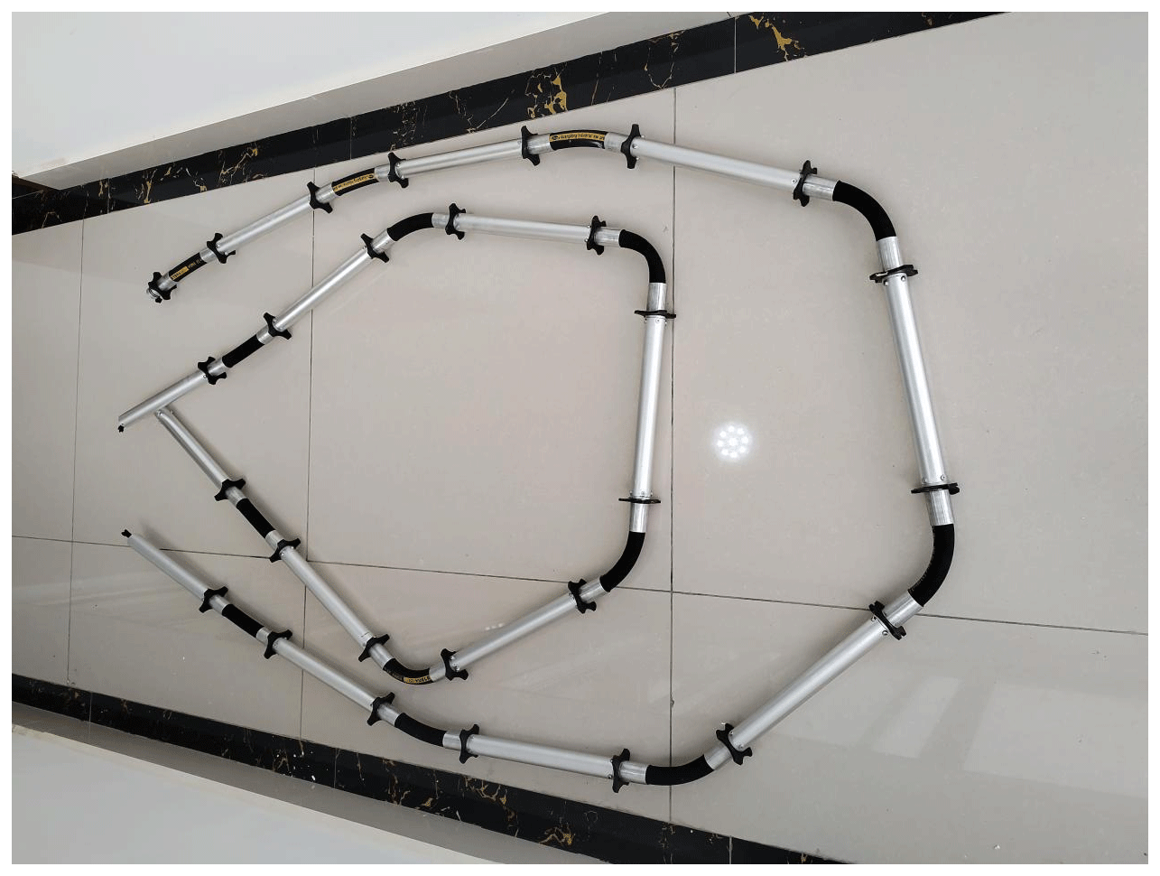
4.3 The interconnection of sensors
After calibrating each sensor, the sensors are sequentially connected using high-strength flexible connectors to form a complete instrument assembly (as shown in Fig. 9).
5.1 Experimental objective
A demonstration site for monitoring deep-seated landslide displacement was established in Baiyan 3 Group, town of Lujiang, city of Baoshan, Yunnan Province, using the flexible measurement array for deep-seated displacement. The main objectives of this field experiment were as follows.
-
Testing the reliability of flexible joint connections.
In the field experiment, the flexible measurement array was installed in a borehole with a depth of 25.4 m, and a ∅ 50 PVC pipe was used for fixation inside the borehole. The instrument, consisting of 14 sensors, was connected through flexible high-strength joints. The first sensor was placed at a depth of 4 m inside the borehole, while the 14th sensor was positioned at 11 m. After the instrument was properly set up, the PVC pipe was filled with fine sand. The experiment confirmed the normal functioning of the instrument, demonstrating the feasibility of this connection method.
-
Testing the installation orientation of the measurement array inside the borehole.
Due to the inherent connection errors, the orientations of the 14 sensors may not be perfectly aligned. However, once the sensors are fixed inside the borehole, their orientations remain fixed. Any deformation or displacement of the landslide will result in changes in the sensor readings and orientations. By analyzing these changes, the distance and direction of the landslide movement can be determined.
-
Testing the reliability of the measurement array in a damp environment inside the borehole.
The borehole environment tends to be cool and humid, and although the instrument is sealed, there may still be moisture inside the instrument probe, which could potentially corrode electronic components. The reliability of the instrument in such conditions needs to be evaluated over time.
-
Testing the stability and durability of the measurement array powered by a battery in the field.
Due to limitations in power supply options and safety considerations, the instrument cannot be powered by 220 V AC electricity in the field. Instead, a 12 V battery is used, which is charged by a solar panel. After a period of operation, the stability and durability of the instrument under battery power in the field are evaluated and assessed.
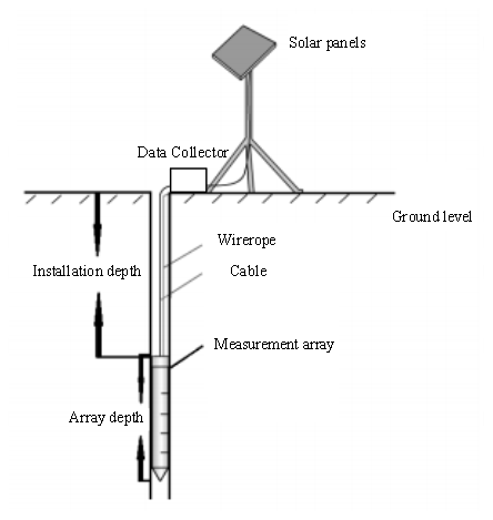
5.2 Installation method
In this field experiment, the installation schematic of the flexible measurement array is shown in Fig. 10. The flexible measurement array is fixed at the predetermined depth position using wellhead steel-wire ropes and then filled with drilling mud to achieve coupling between the measurement array and the rock wall. The measurement data are transmitted through cables to the wellhead data acquisition device, which packages and organizes the data before sending them to the server. The wellhead is equipped with a solar charger to provide power for the underground measurement array and the wellhead data acquisition device.
5.3 Data analysis
After the installation and commissioning of the equipment, the project team initiated the automated monitoring and early warning work. The average value of the data transmitted by the equipment on the first day was taken as the initial data, and subsequent data points were extracted at typical time intervals based on the deformation conditions for the purpose of constructing deformation curves.
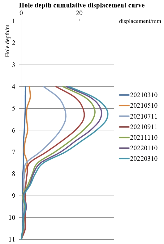
As shown in Fig. 11, analysis of the data curves reveals that from March to May 2021, there was minimal deformation in the deep-seated displacement of the landslide. However, during the flood season, a deformation of approximately 10 mm occurred between depths of 5.5 and 8 m on the slope. This was followed by an accumulated deformation of 23 mm until 11 September. Subsequently, the deformation gradually converged. The increasing displacement observed between depths of 5.5 and 8 m indicates movement along the main sliding direction of the landslide. Conversely, a decrease in displacement was observed between depths of 4 and 5.5 m due to the shifting movement of the sliding zone at 5.5 m. Below 5.5 m, the sensors recorded movement along the main sliding direction, while above 5.5 m, the sensors detected a reverse inclination caused by the movement of the sliding zone, leading to a decrease in measured displacement by the upper sensors. This method of analyzing the deep-seated displacement curve serves as a primary means to identify the position of the sliding zone.
Based on the deformation curve, it can be concluded that there is a distinct sliding zone between depths of 5.5 and 8 m in the landslide. Additionally, notable displacement variations occurred during the flood season. This variation aligns with the concentrated rainfall in the region where the landslide is located, confirming that rainfall is the main triggering factor for the landslide. The deformation curve further demonstrates the accurate monitoring capability of the flexible measurement array for deep-seated landslide displacement, surpassing traditional devices with a limited number of sensors. It provides a more precise and comprehensive measurement of displacement variations throughout the entire borehole depth.
The multidimensional, multi-sliding surface measurement of deep-seated displacement on landslides poses a significant technical challenge in landslide monitoring and early warning. This study developed a flexible measurement array capable of measuring the deep-seated displacement of landslides in full boreholes. It incorporates an azimuth measurement module, eliminating the need for traditional inclinometer pipes and pulley components for auxiliary installation. This advancement greatly enhances cost-effectiveness and measurement accuracy. The maximum measuring range for inclination angle is ±90°, with an accuracy of 0.1 % F ⋅ S, while the accuracy for azimuth angle measurement is 1 % F ⋅ S ° when the drilling top angle is greater than 3°.
The flexible measurement array for deep-seated landslide displacement can be widely applied to the monitoring of slope stability, landslide bodies, embankments, highways, and impermeable walls, capturing inclinations, horizontal displacements, and settlement deformations. When integrated with automated data acquisition equipment, continuous monitoring can be seamlessly automated. Furthermore, by strategically implementing multiple sensor arrays, we can acquire precise displacement magnitude and displacement orientation curves for numerous measurement points. This adaptable measurement configuration surpasses the constraints of traditional fixed inclinometers, which might offer limited probe quantities or suffer from inaccurate installation positions, thereby failing to accurately depict the landslide body's deformation trend. Additionally, it eliminates the requirement for supplementary installation accessories, such as pulleys and inclinometer pipes, consequently simplifying both the mechanical structure and installation procedures. This advancement represents an improvement in both the technology and measurement methods, providing a more comprehensive and enhanced monitoring tool for disaster prevention and mitigation, thereby elevating the level of geological hazard monitoring and early warning technology.
The data and source code used for this study can be obtained by contacting the corresponding author.
Conceptualization: YL, QG. Methodology, data analysis: YL, ZL. Project administration: YL. Writing, visualization: YL, YL, DZ. Review and editing: YL, DZ.
The contact author has declared that none of the authors has any competing interests.
Publisher's note: Copernicus Publications remains neutral with regard to jurisdictional claims made in the text, published maps, institutional affiliations, or any other geographical representation in this paper. While Copernicus Publications makes every effort to include appropriate place names, the final responsibility lies with the authors.
We thank the reviewers for reviewing this paper, and we also thank Yanial Zhao for the mechanical processing and component assembly work.
This research has been supported by the China Geological Survey, Ministry of Natural Resources (grant no. DD20230447).
This paper was edited by Ralf Srama and reviewed by two anonymous referees.
Erik, W. B. and Garry, K. C.: Interpretation of borehole-inclinometer data: a general theory applied to a new instrument, J. Glaciol., 38, 113–124, https://doi.org/10.3189/S0022143000009655, 1992.
Giuseppe, R., Luigi, G., Paola, R., and Francesco, M.: A Multi-Module Fixed Inclinometer for Continuous Monitoring of Landslides: Design, Development, and Laboratory Testing, Sensors, 20, 1–19, https://doi.org/10.3390/s20113318, 2020.
Li, Y., Meng, H., Dong, Y., and Hu, S.: Main Types and characterisitics of geo-hazard in China – Based on the results of geo-hazard survey in 290 counties, The Chinese Journal of Geological Hazard and Control, 15, 29–34, https://doi.org/10.3969/j.issn.1003-8035.2004.02.005, 2004 (in Chinese with English abstract).
Li, Y., Fu, P., Li, Z., Li, X., and Lin, Z.: Biaxial angle sensor calibration method based on artificial neural network, Chem. Engineer. Trans., 46, 361–366, https://doi.org/10.3303/CET1546061, 2015.
Li, Y., Fu, P., Ji, W., Shi, S., Zhang, Y., and Zhang, T.: Predictive method of nonlinear system based on artificial neural network and SVM, Oxid. Commun., 39, 1226–1235, 2016.
Liu, C.: Theory and practice of prevention and control of major geological disasters, The Chinese Journal of Geological Hazard and Control, 23, 126–126, https://doi.org/10.3969/j.issn.1003-8035.2012.01.026, 2012 (in Chinese with English abstract).
Liu, C., Shen, W., and Huang, S.: Some Viewpoints on Strategies in Risk Reduction of Geological Disasters in China, Journal of Catastrophology, 37, 1–4, https://doi.org/10.17993/3cemp.2023.120151.186-205, 2022 (in Chinese with English abstract).
Liu, Y.: Design of the Drilling Trajectory Measurement Device in Ultra-high Temperature based on FOG and its Key Technologies Research, Sichuan university, 2016.
Ministry of Natural Resources of the People's Republic of China: China Institute of Geo-Environment Monitoring (2022) Bulletin of geologic hazards from January to December in 2022, China Institute of Geo-Environment Monitoring, Beijing, 2022.
Sarolkar, P.: Disasters and Hazards: Risk Reduction, Mitigation and Management, Journal of Geosciences Research, 7, 10–21, https://doi.org/10.56153/g19088-022-0002-r, 2022.
Stark, T. D. and Choi, H.: Slope inclinometers for landslides, Landslides, 2008, 1–5, 2008.
Stark, T. D., Arellano, W. D., Hillman, R. P., Hughes, R. M., Joyal, N., and Hillebrandt, D.: Effect of Toe Excavation on a Deep Bedrock Landslide, J. Perform. Constr. Fac., 19, 244–255, https://doi.org/10.1061/(ASCE)0887-3828(2005)19:3(244), 2005.
Vassallo, R., Calcaterra, S., Rosa, J. D., Maio, C. D., and Gambino, P.: Long-Term Displacement Monitoring of Slow Earthflows by Inclinometers and GPS, and Wide Area Surveillance by COSMO-SkyMed Data, Geosciences, 10, 171, https://doi.org/10.3390/geosciences10050171, 2020.
Yin, Y. and Wu, S.: Research on landslide monitoring, early warning and emergency prevention technology, Beijing, Science Press, ISBN 9787030363947, 2012 (in Chinese).
Zhou, C., Liu, Y., and Chen, W.: Development of Deep Landslide Displacement Monitoring Instrument with the Function of Torsion Direction Measurement, Drilling Engineering, 40, 5–7, https://doi.org/10.3969/j.issn.1672-7428.2013.07.003, 2013 (in Chinese with English abstract).
Zhou, P.: Indicator system and techniques of landslide monitoring, Journal of Geomechanics, 10, 19–26, https://doi.org/10.3969/j.issn.1006-6616.2004.01.003, 2004 (in Chinese with English abstract).