the Creative Commons Attribution 4.0 License.
the Creative Commons Attribution 4.0 License.
 | 05 Mar 2025
A steerable system for the RECoverable Autonomous Sonde (RECAS) to access and study subglacial lakes
Mikhail A. Sysoev
Xiaopeng Fan
Nan Zhang
Da Gong
Yang Yang
Ting Wang
Zhipeng Deng
The study of subglacial lakes requires clean access and sampling technologies. One of the most promising alternatives is the newly developed thermal drill, the RECoverable Autonomous Sonde (RECAS), which allows downward and upward ice drilling and subglacial water sampling while the subglacial lake remains isolated from the surface. The original sonde descends downward under the force of gravity, and the borehole trajectory cannot be controlled. However, in certain cases, the sonde would preferably be able to drill at specific angles and directions, enabling it to follow a desired trajectory (e.g., maintaining verticality within the desired range) or bypass obstacles in the ice (e.g., stones and other inclusions). The general principle for the steering RECAS is to adjust the voltage for the electric thermal head heaters, which provides an opportunity to control the heat distribution on the thermal head surface, thereby altering the borehole trajectory during drilling. In this paper, the general principles of the steering RECAS are described, and experimental results on deviational ice drilling with a controllable electric thermal head are discussed.
- Article
(9855 KB) - Full-text XML
-
Supplement
(2059 KB) - BibTeX
- EndNote


It is now widely accepted that subglacial hydrological environments are similar to the water distribution found elsewhere on Earth's surface and comprise a vast network of lakes, rivers, and streams located thousands of meters beneath ice caps, glaciers, and the Antarctic and Greenland ice sheets (Bowling et al., 2019; Siegert et al., 2012a; Ashmore and Bingham, 2014). A subglacial lake is considered to be any large body of liquid water existing below an ice mass. The water depth of subglacial lakes varies from a few to several hundred meters (Wright and Siegert, 2011). As of 2022, a total of 773 subglacial lakes were identified, including 675 in Antarctica, 64 in Greenland, two beneath the Devon Ice Cap, six beneath Iceland's ice caps, and 26 in valley glaciers (Livingstone et al., 2022). The ice thickness above subglacial lakes may vary from several tens to thousands of meters.
Subglacial lakes provide unique information regarding paleoclimatic conditions, basal hydrology, biogeochemical fluxes, and geomorphic activity. It is anticipated that subglacial lakes harbor relict microbial species capable of thriving in complete darkness, low nutrient levels, high water pressure, and isolation from the atmosphere (Skidmore, 2011). In situ investigations should not contaminate these subglacial aquatic systems. Currently, hot-water drilling systems are considered the cleanest method for accessing subglacial lakes. US teams successfully accessed the Whillans and Mercer subglacial lakes on the coastal margin of West Antarctica in early 2013 and during the 2018–2019 season, demonstrating the well-proven effectiveness of this technology (Priscu et al., 2021; Tulaczyk et al., 2014).
However, access technology using hot-water drilling systems has several significant limitations. For instance, these systems necessitate complicated methods to filter and subject high-speed hot-water flow (> 150–200 L min−1) to ultraviolet (UV) treatment at the surface. Additionally, they are extremely bulky and highly power-consuming. For example, all drilling and auxiliary equipment for exploring of subglacial Lake Ellsworth in West Antarctica weighed approximately 60 t, and the fuel supplies weighed a further approximately 55 t (Siegert et al. 2012b). To simplify the drilling process and decontamination of drilling tools, we propose accessing and studying subglacial lakes with a freezing-in electric thermal drill – the RECoverable Autonomous Sonde (RECAS) – capable of downward and upward ice drilling and subglacial water sampling while ensuring that the subglacial lake remains isolated from the surface (Talalay et al., 2014). RECAS is estimated to be 10–20 times less expensive than penetration with a hot-water drilling system, and its installation and operation require only four specialist staff members (Sun et al., 2023) vs. at least 10 staff members required to run a deep hot-water drill (Siegert et al., 2012b). The whole RECAS system, containing the sonde, winch, generator, and other components (excluding the fuel supply), weighs about 6.2 t. The sonde surface is thoroughly cleaned before deployment. Although the sonde might drag native microbes, which are embedded in ice, into subglacial targets at various depths as they melt, this occurs in a predictable manner (Schuler et al., 2018). Two concepts similar to RECAS have been proposed by Stone Aerospace, a US engineering company (Pereira et al., 2023; Stone et al., 2018), and Aachen University in Germany (Heinen et al., 2021).
The RECAS was successfully tested in East Antarctica during the 2021–2022 field season, reaching the ice sheet base at a depth of 200.3 m, sampling basal meltwater and measuring its pressure, temperature, pH, and conductivity before returning to the ice surface (Sun et al., 2023). To expand the sonde's capabilities, we propose equipping it with a steering technique to control and guide the drilling process. This allows drilling at specific angles, depths, and directions, enabling the sonde to follow a desired trajectory (e.g., maintaining verticality within the desired range) or bypass obstacles in the ice (e.g., stones and other inclusions). A similar system was implemented in the IceMole probe (Dachwald et al., 2014). IceMole has an original steering system consisting of a combined thermomechanical drill head and controlled lateral heating. However, the probe is significantly shorter (1 or 2 m in length), has a square cross-section, and can only operate in dry boreholes (maximum drilling depth ∼ 25 m), which differs greatly from the operating conditions of RECAS. Due to the complexity of adapting the IceMole system to RECAS, we developed an original steering system. Herein, we describe the general principles of the steering RECAS and discuss the experimental results on deviational ice drilling with a controllable electric thermal head.
2.1 General concept of the steering RECAS
The RECAS comprises four major systems: a heating system (consisting of an upper thermal head, a lower thermal head, and lateral heaters), an inner winch system, a scientific load platform, and a monitoring and control system (Sun et al., 2024). The upper and lower thermal heads are identical except for the central hole of the cable in the top thermal head (Li, 2020). Thus, it can drill both downward and upward and move within the borehole using an inner cable-recoiling mechanism, similar to how a spider climbs on its silk line.
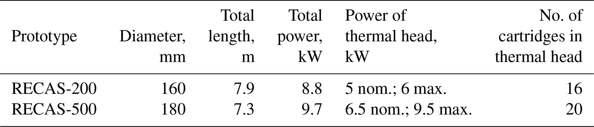
Two RECAS prototypes were developed: RECAS-200, with a 200 m long cable inside, and RECAS-500, with a 500 m long cable inside. The RECAS-500 design is shown in Fig. 1. The prototypes differed not only in their drilling ability but also in their size, their power consumption, the number of cartridges in the thermal head, and other factors (Table 1). In both prototypes, all heaters are supplied simultaneously at the same voltage from a single source.
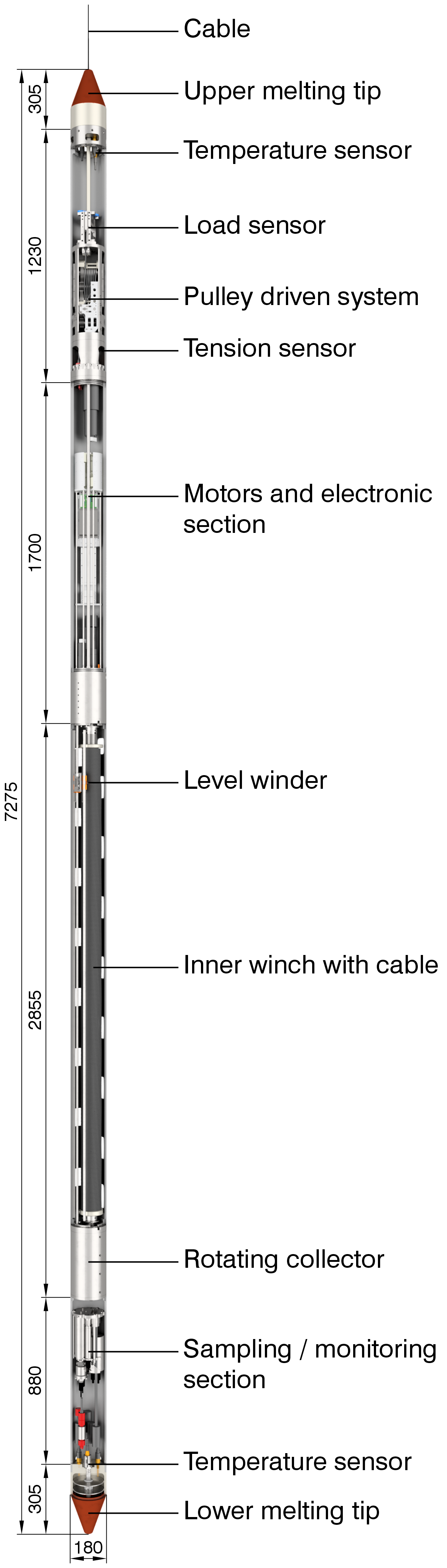
Figure 1General schematic of the RECAS-500 with a 500 m long cable inside (all dimensions are in mm.)
The fundamental principle behind an adjustable electric thermal head is to control the voltage supplied to each pair of adjacent heaters. This enables control over the heat distribution on the thermal head surface and allows borehole deviations during drilling. Furthermore, controlling the heat distribution of the thermal head makes it possible to equalize the load on the heaters as needed. Heating cartridges exhibit variations in their parameters owing to their technological tolerances. Additionally, these parameters may change slightly during long-term use, and heating cartridges can fail because of their long-term use or manufacturing defects.
The sonde is steered using data from an inclinometer installed inside it. The data from the inclinometer are transmitted to a personal computer (PC), processed, and converted into pulse-width modulation (PWM) coefficients, which determine the PWM duty cycle for a specified number of channels. In the subsequent tests using the RECAS-200 prototype, the PC will be replaced with a microcontroller mounted inside the sonde. The PMW coefficients are transmitted from the computer to a PWM generator (Sect. S2 in the Supplement) inside the sonde prototype, where an individual PWM signal is generated for each channel. Each PWM signal is amplified using a power module (Sect. S3 in the Supplement) and supplied to the corresponding heater inside the thermal head. The PWM signal duty cycle limits the heater power.
It was decided to implement three control modes: manual mode, where the heater configuration can be set manually; semiautomatic mode, where the configuration is “linked” to the tilt angle of the sonde; and automatic alignment mode, where the system will “attempt” to align the sonde with a vertical position and/or maintain the sonde vertically.
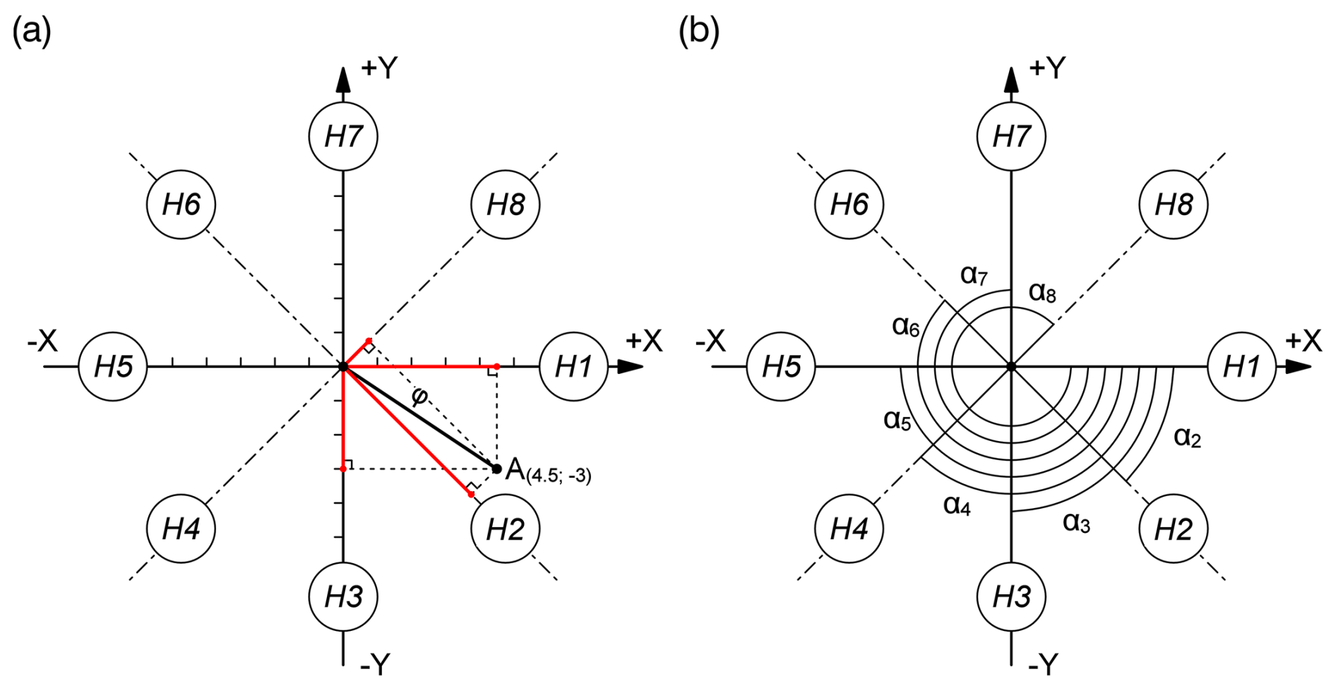
Figure 2Schematic diagram of the relative location of the heater pairs (H1–H8) and the inclinometer in the sonde prototype. (a) Projection length l and (b) heater pair axis angle α.
2.2 RECAS positioning estimation
The following method was employed to convert the values received from the inclinometer into PWM coefficients for automatic alignment mode. The inclinometer transmitted deviation values in degrees along the X and Y axes. As shown in Fig. 2, the X and Y axes correspond to the inclinometer axes in the horizontal plane. Point A indicates a deviation, with X = 4.5 and Y = −3, for instance. Eight pairs of 16 heaters are shown schematically in the form of circles, designated as H1–H8.
First, the absolute inclination ϕ is determined (Eq. 1). This value is required not only for subsequent calculations but also for monitoring purposes.
where X and Y are the coordinates received from the inclinometer.
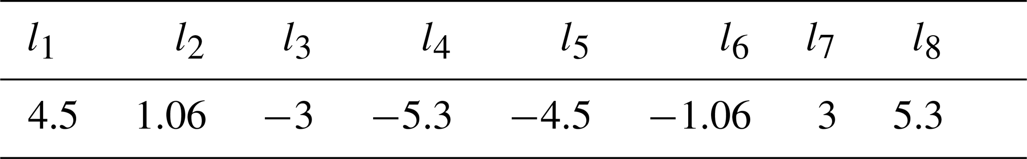
Next, the projection length values ln of ϕ on the axis of each heater pair are determined as follows (indicated in red in Fig. 2a):
where αn is the heater pair axis angle relative to the X axis (Fig. 2b).
To obtain the required PWM coefficients, the ln values must be converted to relative values in the range of 0–1. Additionally, it is necessary to be able to adjust the resulting coefficients. For this purpose, a logistic function (logistic curve) was used (Kyurkchiev and Markov, 2015). After slight adaptation to meet our conditions, the final equations take the following form:
where Kn is the PWM coefficient for each heater pair, V is the intermediate coefficient, T is the correction coefficient (above zero), and yoff is the offset coefficient (0–1).
T and yoff are used to adjust the final values. The coefficient yoff limits the maximum average PWM coefficient value (i.e., with zero inclination and yoff = 0.5, all PWM coefficients will be 0.5). Meanwhile, the correction coefficient T affects the rising section length where the derivative is relatively large. The influence of T and yoff on the final results is illustrated by the example discussed next.
2.3 RECAS positioning calculation example
For the calculation example, random inclinometer values are taken as X = 4.5 and Y = −3. Then, absolute inclination is
The α values for eight heater pairs are presented in Table 2.

The projection length of ϕ for the first heater pair is estimated as
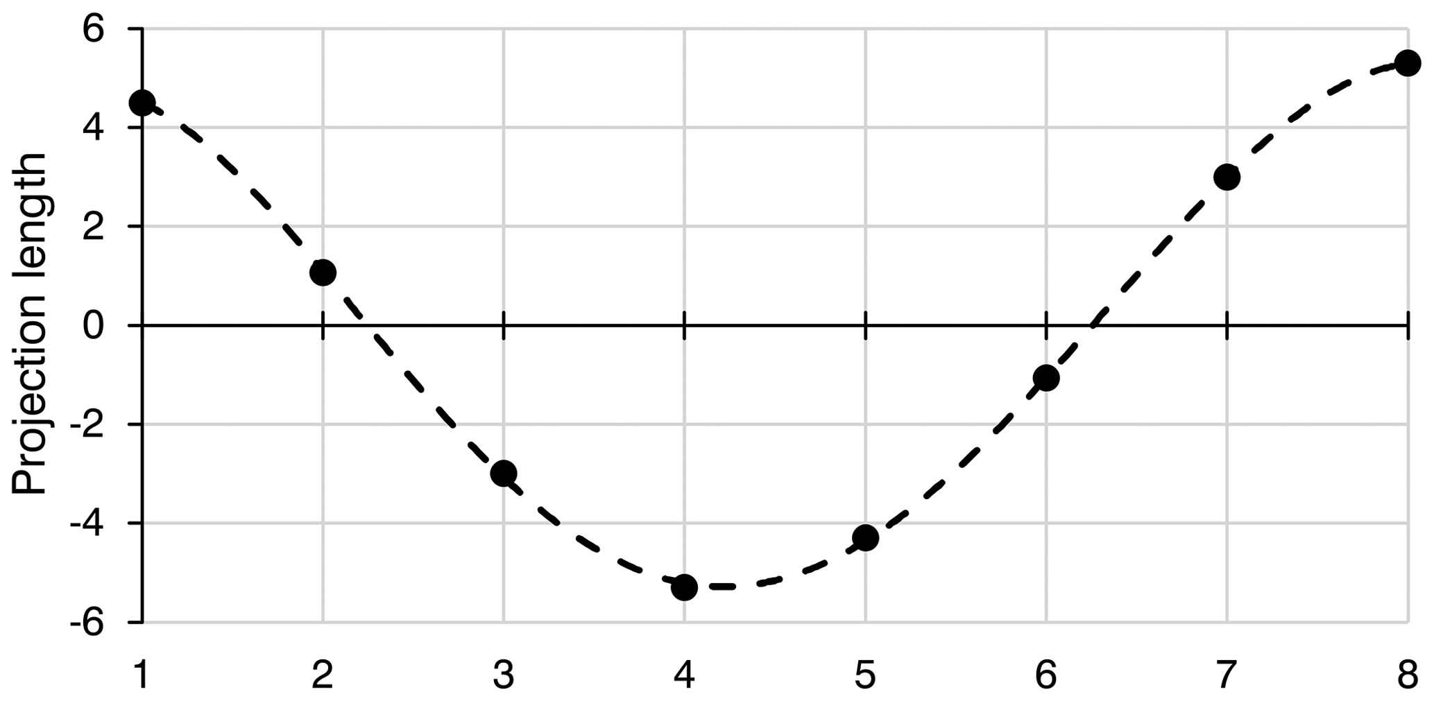
The calculation results for all eight projection length values are listed in Table 3 and shown in graph form in Fig. 3.
For this example, the following coefficients were selected: T = 1 and yoff = 0.8. Then, the intermediate and PWM coefficients for the first heater pair are
The results of the final PWM coefficient calculations are listed in Table 4.
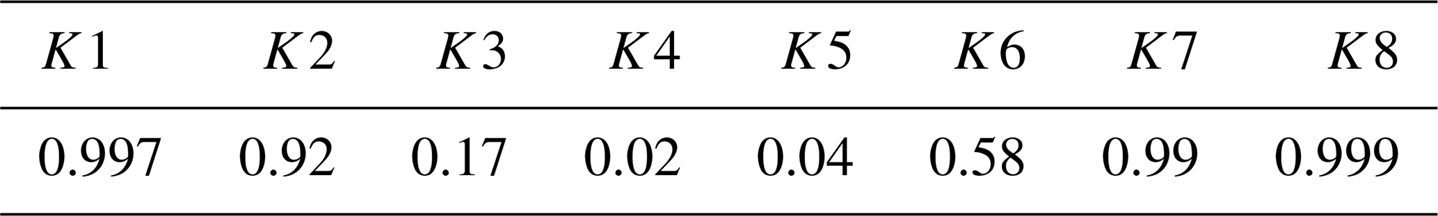

Figure 4PWM coefficients at constant X = 4.5, Y = −3, and yoff = 0.5 for three different values of T: T = 0.5, T = 1, and T = 2.
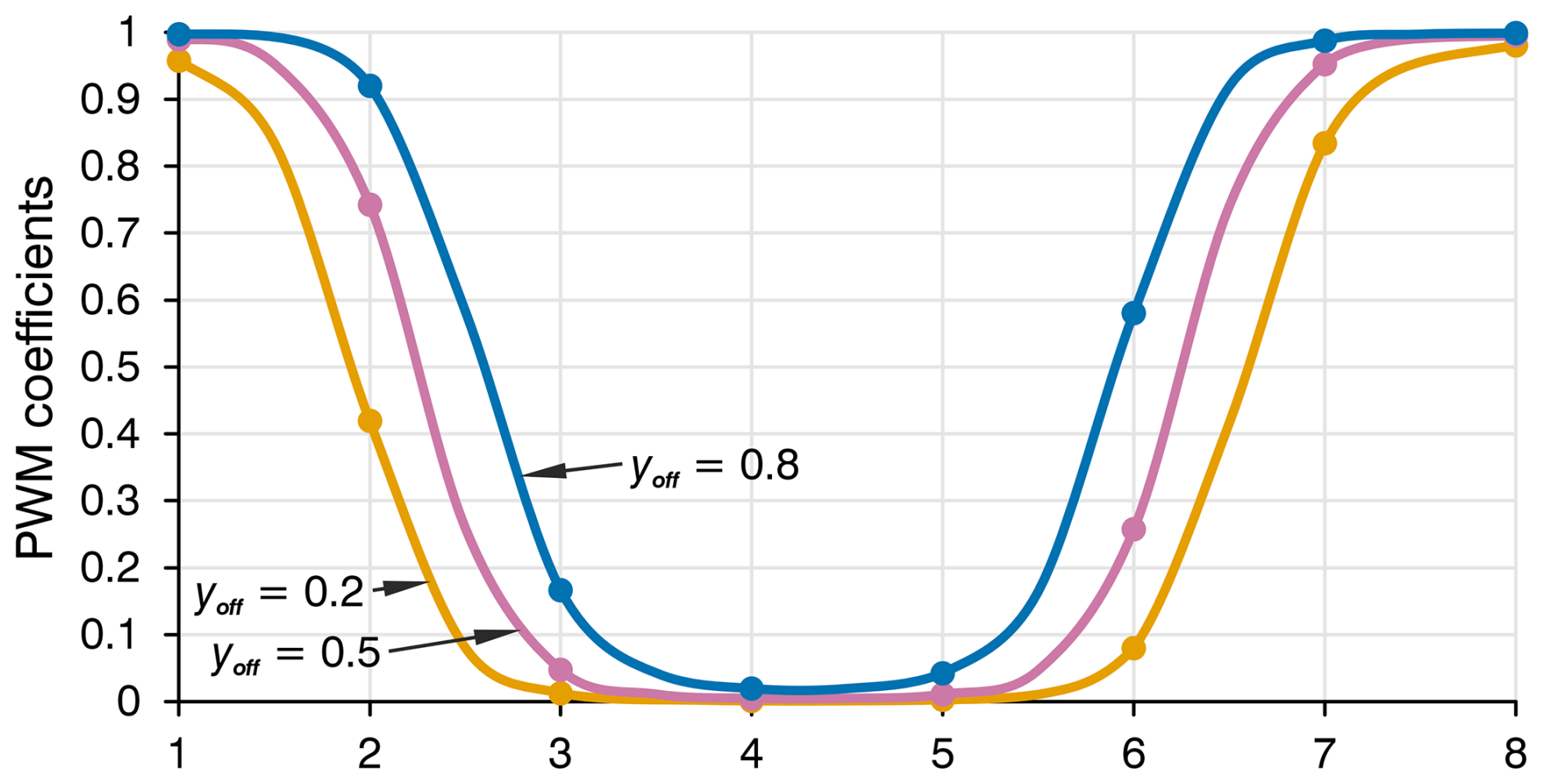
Figure 5PWM coefficients at constant X = 4.5, Y = −3, and T = 1 for three different values of yoff: yoff = 0.2, yoff = 0.5, and yoff = 0.8.
To illustrate how T and yoff affect the final PWM coefficients, the calculation results with the same deviation values but different T and yoff values are presented in Figs. 4 and 5.
The coefficients T and yoff should be selected experimentally. Therefore, they do not need to remain constant. They may depend on other parameters; for example, yoff may depend on the absolute inclination. It is worth noting that when the correction coefficient T approaches zero, all PWM coefficients tend towards the yoff value, which means that the heat distribution on the thermal head surface approaches a uniform pattern.
Before changing the borehole trajectory direction, determining the passability of the sonde in the drilled borehole is essential. Owing to its length exceeding 7 m, the RECAS has a high likelihood of becoming stuck in the borehole, even with relatively small deviations. The main parameter affecting sonde passability in a curved borehole is the deviation intensity. To characterize the borehole deviation intensity at a specific interval along its axis, the relative zenith angle values were used, considering the interval between their measurement points. Therefore, the zenith deviation intensity was determined as follows (Zvarygin, 2011; Shamshev et al., 1983):
where Δθ is the relative zenith angle in degrees and ΔL is the borehole axis interval length.
If the deviation intensity at some borehole interval remains constant (iθ = const), it means that the borehole is curved along a circular arc at a certain interval. The borehole radius of curvature R depends on the deviation intensity, as follows (Zvarygin, 2011) (Fig. 6).
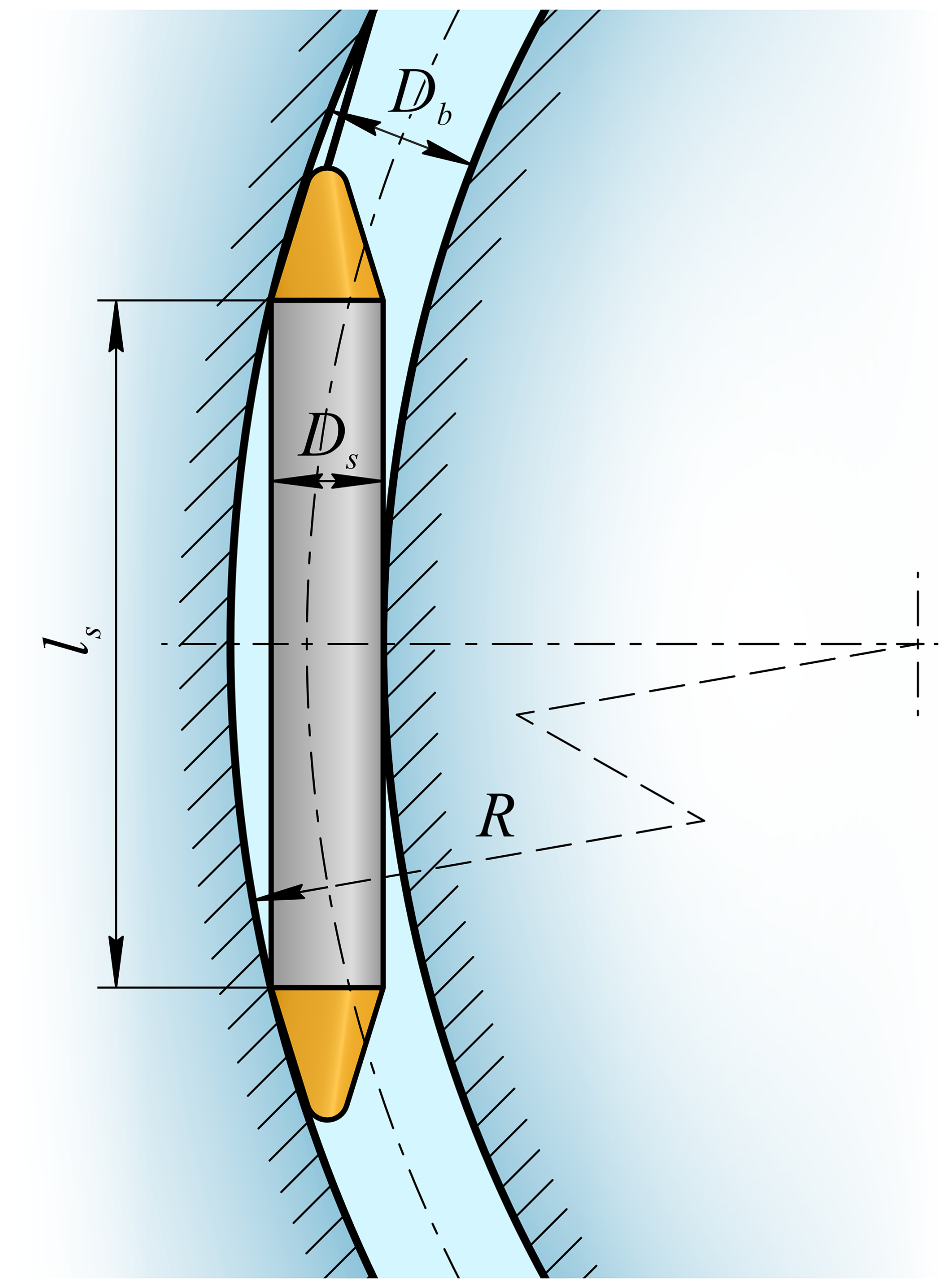
The passability of a sonde in a borehole interval with a known diameter and radius of curvature can be determined as follows:
where ls is the length of the cylindrical part of the sonde (the thermal head length is not included), Ds is the sonde diameter, and Db is the borehole diameter.
As the borehole radius of curvature is considerably larger than the gap between the sonde and borehole diameters, Eq. (6) can be simplified as follows (Shamshev et al., 1983).
Based on RECAS field tests, the difference between the borehole and sonde diameters is 10–20 mm. This clearance mainly depends on the rate of penetration (ROP), and additional laboratory tests are required to establish a more precise relationship. Considering that the RECAS length is approximately 7 m, the radii of curvature ensuring RECAS passibility are in the range of 300–600 m.
Therefore, it is not sufficient to simply monitor the borehole inclination to prevent the RECAS from being stuck in the borehole. Instead, it is necessary to continuously estimate the deviation intensity, the borehole radius of curvature, or both at an interval from the bottom hole with a length approximately equal to that of the sonde.
4.1 Testing stand
4.1.1 General testing stand design
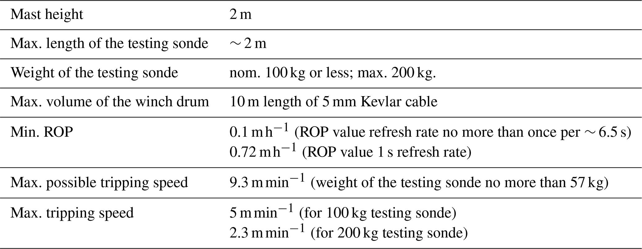
The testing stand consists of a sledge, mast, top wheel, winch, and sonde prototype (Fig. 7). All stand parts are mounted on a sledge, which has a modular construction comprising a pair of skis and two welded frames bolted together. A 2 m high mast is mounted in the middle of the sledge. A small winch is mounted near the mast on a sledge. A block is installed at the top of the mast. The testing stand parameters are listed in Table 5.
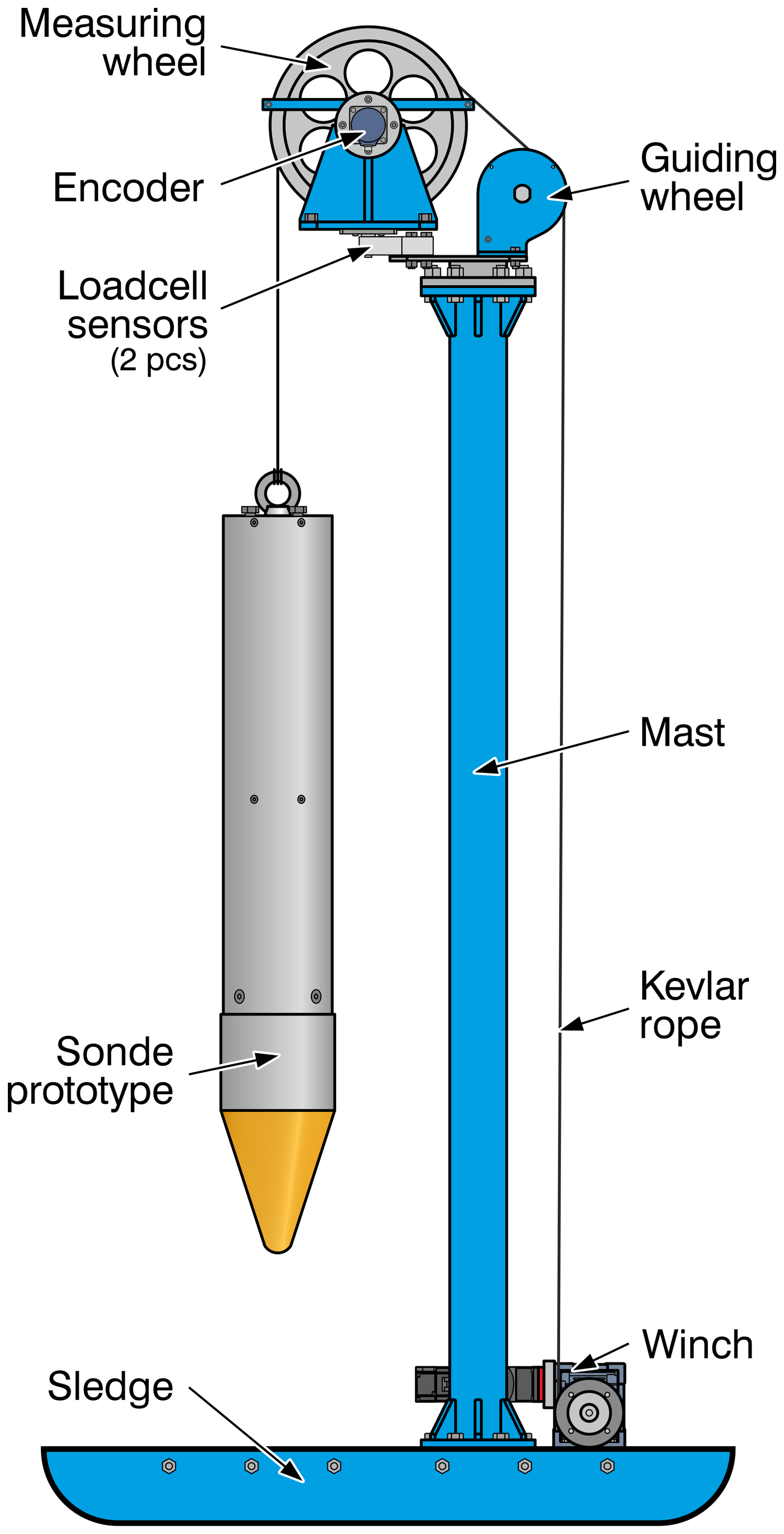
4.1.2 Top block and ROP as low as practicable
The top block consists of two wheels – a measuring wheel and a guiding wheel, an encoder, and two load-cell sensors. The measuring wheel is designed for a rope with a 5 mm diameter so that the cable length passing through the wheel per revolution equals 1 m ± 1 mm. This design simplifies the calculation and further adjustment of the measuring equipment. The guiding wheel is used to guide the rope from the winch to the measuring wheel.
To register the weight on bit (WOB), two load-cell sensors are installed underneath the measuring wheel assembly. Each sensor can withstand a force of up to 100 daN. To measure the ROP, an encoder with a resolution of 5000 measurements per revolution (MPR) is installed on the measuring wheel shaft. As the ROP is expected to be relatively low, the angular rotation speed of the measuring wheel is correspondingly small. Therefore, the higher the encoder resolution, the more frequently it can capture instantaneous low ROP values.
As-low-as-practicable ROP [m h−1] can be estimated as follows:
where D is the wheel diameter (D = 0.3135 m), d is the rope diameter, and nmin is the minimum angular velocity in revolutions per second (RPS).
The minimal angular velocity nmin is equal to
where m is the encoder resolution in MPR and t is the time after which the data must be updated (in this study, t = 1 s).
The diameter of the rope axis on the wheel is
where l is the rope length passing through the wheel per revolution.
After all rearrangements, the as-low-as-practicable ROP is
Therefore, the as-low-as-practicable ROP, which can be measured with a 5000 MPR encoder, 1 m wheel circumference, and measurement frequency of once per second, was 0.72 m h−1.
4.1.3 Winch
The winch is based on an RV50 series worm gearbox. For precise winch control, a 200 W power servo drive was chosen in this study. To compensate for the low servo power, a small PX60 series planetary gearbox with a gear ratio of 1:6 was installed between the worm gearbox and servo. The small drum was customized to hold one layer of 5 mm diameter Kevlar rope with a length of 10 m. To simplify the winch construction, the drum was mounted directly on the output shaft of the worm reducer. Further details regarding the winch construction design are presented in Sect. S1 in the Supplement.
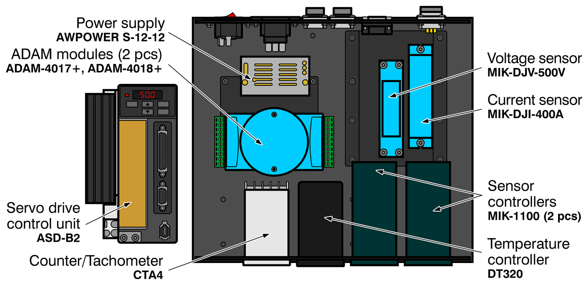
4.1.4 Control system
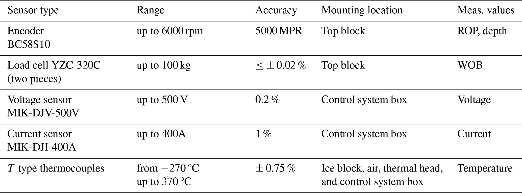
The control system consists of a box containing various data acquisition modules (Fig. 8). Data acquisition modules ADAM 4017+ and ADAM 4018+ were used to collect data from the load-cell sensors and thermocouples, respectively. Counter-tachometer module CTA4001A was used to receive and convert signals from the encoder on the measuring wheel. Two MIK-1100 modules were connected to voltage and current sensors. Temperature module DT320 was used to monitor the sonde prototype thermal head temperature. All modules, along with the voltage and current sensors, were mounted in a BDH20016 black case. The wiring schematics for all components are shown in Fig. S18 in the Supplement (Sect. S5). The sensor parameters are listed in Table 6.
4.1.5 Software
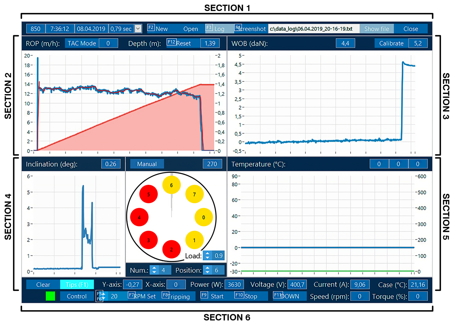
The control system box, servo control unit, and thermal head control unit were connected to a computer via RS-485. The MODBUS RTU communication protocol was used for data transmission. The software registers the following parameters from the sensors connected to the control system box: ROP (m h−1) and depth (m) (Sect. 2 in Fig. 9), WOB (daN) (Sect. 3), current (A), voltage (V), power (W), and three temperatures (°C) (Sect. 5). Through the thermal head control unit, the software allows monitoring of the sonde prototype inclination and heater status and allows selection between manual and automatic modes (Sect. 4). A control panel for the winch is located at the bottom of the screen (Sect. 6).

4.2 Testing the sonde prototype
4.2.1 General structure of the sonde prototype
The sonde prototype consisted of a thermal head borrowed from the RECAS-200 prototype and a control unit assembled inside the housing (Fig. 10). The total sonde prototype length was approximately 1.1 m, and its weight was approximately 35 kg. The sonde prototype was suspended using a Kevlar rope tied to a hook. Electric lines for the power supply and communication were inserted through isolated connectors in the top cover.
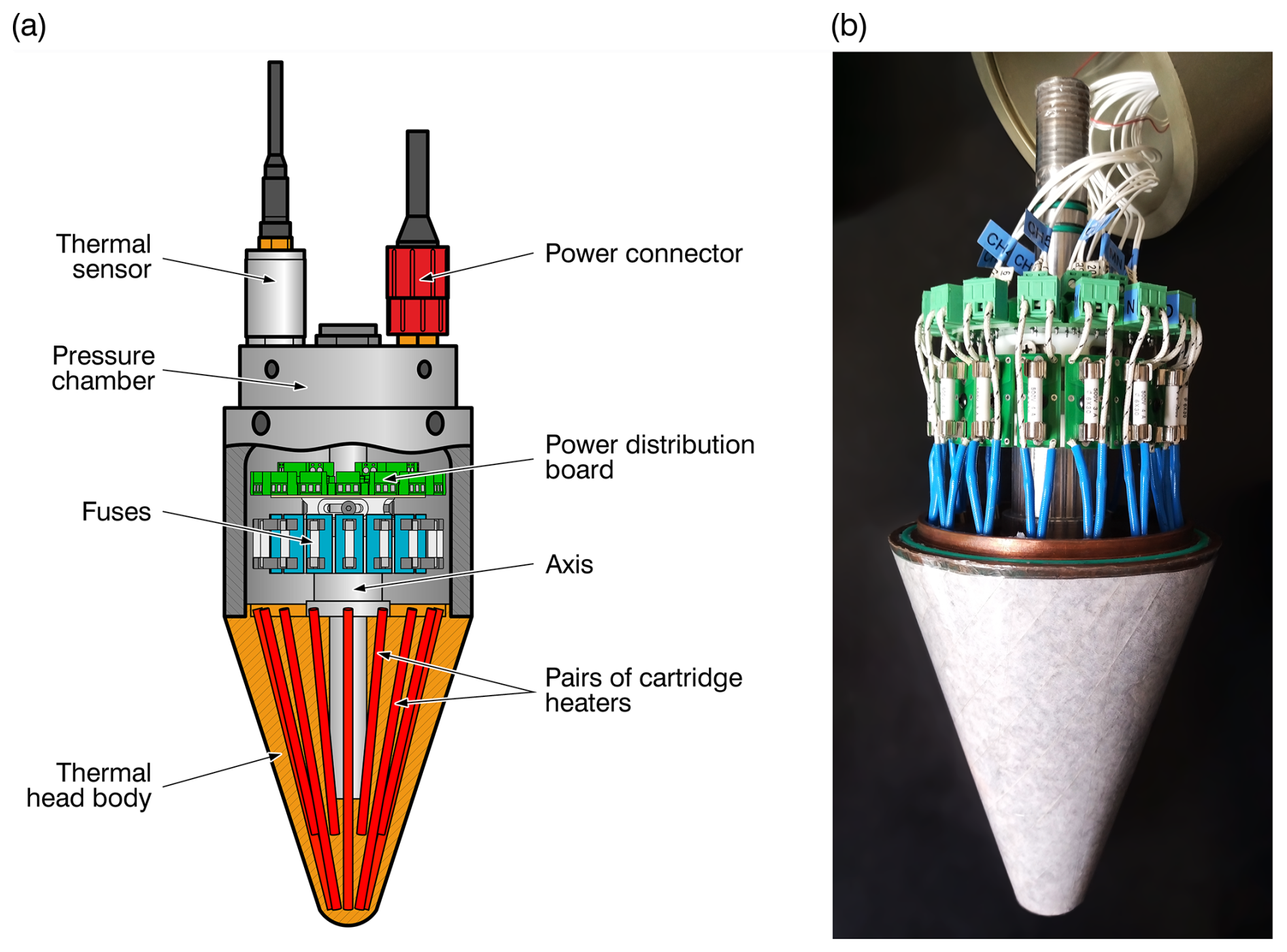
4.2.2 Thermal head
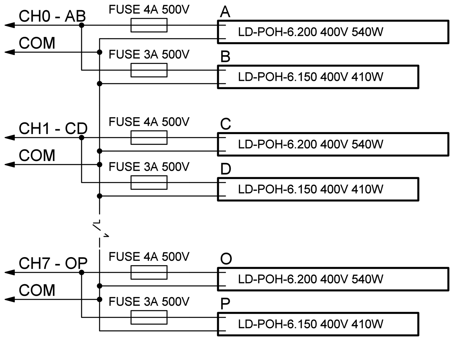
The thermal head diameter was 160 mm. It had 16 heat cartridges with a total power of approximately 7.6 kW (Li et al., 2020; Talalay et al., 2019). The heater connections in the thermal head were redesigned (Fig. 11). Fuses were installed on each heater, and a distribution board was designed to distribute the load and connect it to the power connector (Fig. 12). To allow each heater to be individually connected to a power source, the power connector was also changed from two four-pin connectors to one 21-pin connector.
The thermal head uses eight long heaters (200 mm in length) and eight short heaters (150 mm in length) that were arranged in an alternating pattern. The cartridges were controlled in pairs, with each long heater paired with an adjacent short one (Fig. 12). Therefore, the number of required PWM signals (PWM channels) was reduced to eight.
4.2.3 Control unit
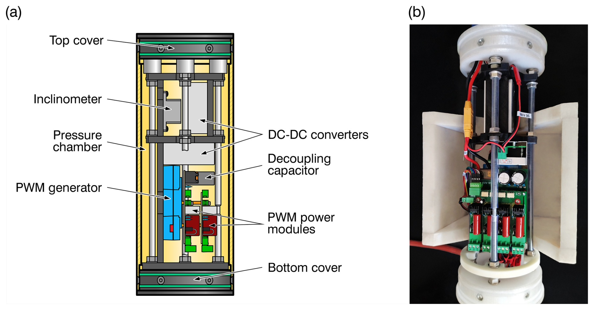
To control the heaters in the sonde prototype, a control unit was designed as a pressure chamber housing the following components (Fig. 13).
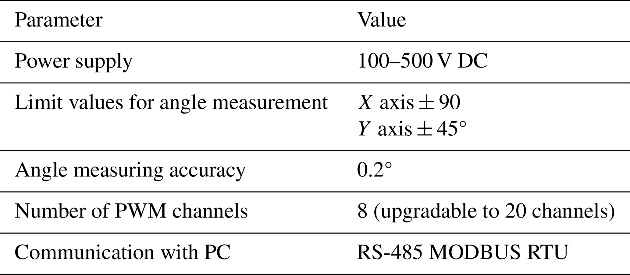
Dual-axis inclinometer. An inclinometer with two axes was chosen instead of a three-axis one because the control unit was rigidly fixed together with the thermal head inside the sonde prototype, eliminating the need to track the relative rotation along the vertical axis. Also, sonde rotation along the axis will not change the steering direction because the system constantly calculates a new PWM coefficient. The task of tracking the borehole azimuth is planned for future RECAS prototype testing.
PWM generator for 20 channels (Sect. S2 in the Supplement). Although only eight PWM channels were required in this study, the PWM generator was designed with 20 channels to enable the control of individual heaters in the bottom thermal head in the RECAS prototype in the future.
Two power modules with four channels each (Sect. S3 in the Supplement). The heater pairs were not connected directly to the PWM generator but through power modules that amplify the corresponding PWM signals from the generator.
Two 15 V DC–DC converters (Sect. S4 in the Supplement). Two identical DC–DC converters were used to isolate the power supply of the inclinometer and the PWM generator from the power supply of the low-voltage part of the power modules.
The wiring schematics for all components are shown in Fig. S19 in the Supplement (Sect. S5 in the Supplement).
All control unit modules, except for the inclinometer, were customized for this study. The primary characteristics of the control units are listed in Table 7.
Further details regarding each individually designed module can be found in the corresponding Supplement.
5.1 Factors and main parameters of experiments
To study the sonde prototype inclination in a drilled borehole, a series of tests were conducted in the Polar Research Center laboratory.
The main factors affecting the sonde inclination and drilling performance are the following:
-
ice temperature (kept constant at −16 °C);
-
environmental temperature (varied slightly between +7 and +12 °C);
-
ROP, which was controlled by the winch and limited by the power supplied to the heaters inside the thermal head; and
-
WOB, which changed with the ROP and was limited by the sonde prototype weight.
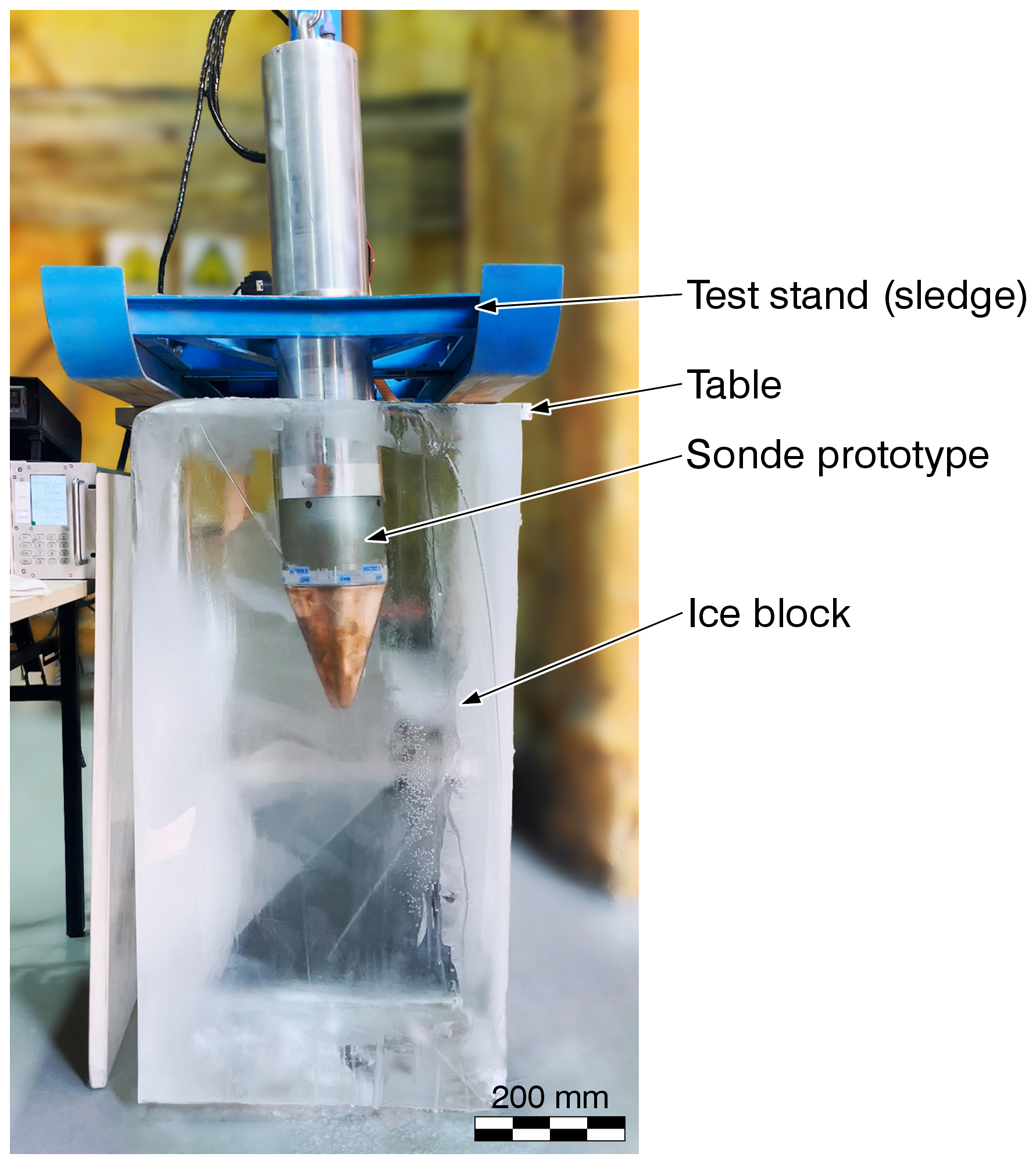
The main parameter to be recorded was the sonde inclination. The sonde inclination was affected by the controlled directional heat distribution on the thermal head surface, which was controlled by limiting the heater power. The control algorithm, with two variable coefficients T and yoff, is described in Eq. (3). Therefore, the main purpose of the experiments was to determine the dependence of the sonde inclination on these coefficients. For clarity and visual control, blocks of transparent ice with dimensions of 50 cm × 50 cm × 100 cm were used in the experiments (Fig. 14).
5.2 Preliminary experiment
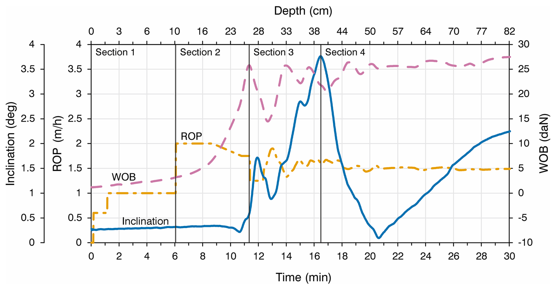
A preliminary experiment was conducted to determine the potential ROP and WOB ranges and the possibility of controlling the sonde prototype inclination in the borehole by regulating the heater power in the thermal head. The experiment recording was divided into four sections (Fig. 15).
Section 1 (0–6 min). The first 200 mm of drilling was strictly vertical, with an ROP of 0.6 m h−1 and all heaters running at 50 % power. Subsequently, the power was increased to the maximum, and half of the heaters on one side of the thermal head were switched off. Then, the ROP was increased to 1 m h−1.
Section 2 (6–11 min). No sonde prototype inclination was detected, and the ROP was set to 2 m h−1 to increase the WOB.
Section 3 (12–16 min). The inclination began to increase rapidly when the WOB value reached approximately 25 daN. An attempt was made to stabilize the WOB at this value. The WOB stabilized at approximately 25 daN with an ROP of approximately 1.5 m h−1.
Section 4 (16–30 min). When the sonde prototype inclination angle reached approximately 4°, the powered heater configuration was changed. Four previously powered heater pairs were switched off, and four heater pairs on the opposite side were switched on. The inclination angle decreased to nearly zero and then gradually increased in the opposite direction.
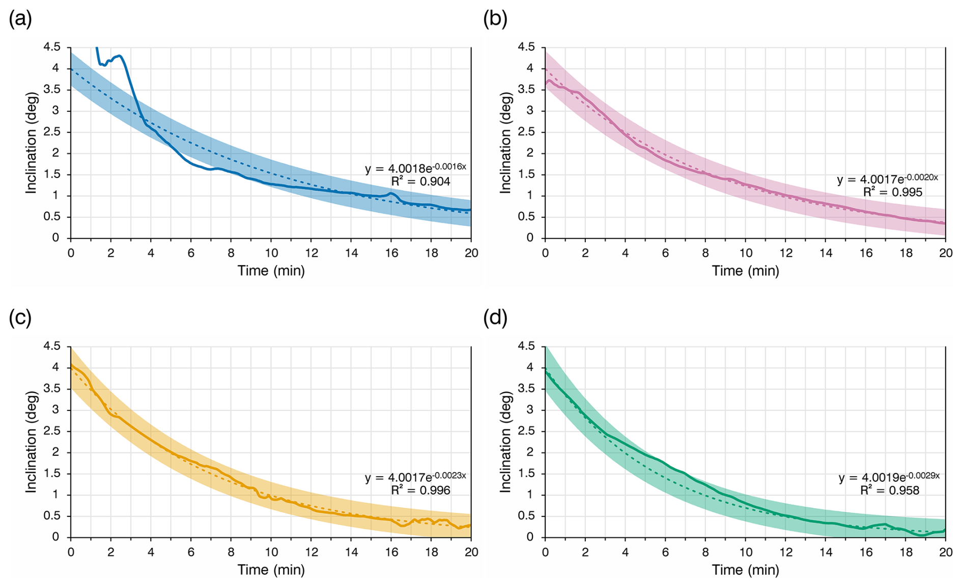
Figure 16Recording of the four experiments with trend lines: (a) Borehole 1, T = 0.5; (b) Borehole 2, T = 1; (c) Borehole 3, T = 1.5; and (d) Borehole 4, T = 2.
Based on the preliminary experimental results, the following conclusions can be drawn. To achieve the desired sonde prototype inclination, the WOB should be approximately 20 daN or higher. However, the test sonde weight was only 35 kg, which significantly reduced the range of acceptable WOB values. To avoid a situation in which the entire sonde prototype weight would be at the bottom of the borehole, the WOB range was limited to 22–28 daN.
When a 50 % power limit was applied, the WOB stabilized at an ROP of approximately 1.5 m h−1. Although WOB is not directly controlled, it depends on the ROP. However, constant WOB adjustments via ROP changes using a proportional-integral-derivative (PID) controller were not very effective because the transients significantly influenced the measured parameters. Therefore, in subsequent experiments, we decided to maintain a constant ROP despite potential WOB fluctuations.
Because the coefficient yoff limits the maximum average PWM coefficient values, in practice, it limits the power consumption of the thermal head, which, in turn, affects the maximum ROP. Preliminary experimental results showed that testing was meaningful only at WOB values close to the maximum. This means that at a certain yoff value, it is not possible to change the ROP over a significant range. By analyzing the “behavior” of Eq. (3) we can conclude that at yoff = 0.5, the heat distribution is the most intense, and the assumed rate of change in borehole trajectory is also at its maximum. The limitation of the maximum borehole depth that can be obtained from the available ice blocks underscores its importance.
Based on the above, we conducted a series of experiments with four different correction coefficient T values. The ROP was kept constant at 1.5 m h−1. The WOB stabilized between 22 and 28 daN. The power consumption was limited to 50 % by setting yoff = 0.5.
According to the test plan, in the first approximately 300 mm of each experiment, the sonde prototype should drill with half of the heaters on one side turned off until the sonde inclination angle reaches approximately 4° (Ye et al., 2024). Subsequently, the automatic alignment mode will be enabled. The algorithm will recalculate the PWM coefficients of the heaters at 1 s intervals. It is worth noting that decreasing the PWM coefficient recalculation frequency (i.e., slowing the response to inclination angle changes) can influence the borehole deviation intensity. A decrease in the recalculation frequency is likely to result in a decrease in borehole deviation intensity.
5.3 Experimental results and discussion
A total of four experiments were performed. The experimental recordings are shown in Fig. 16. As the values were recorded from the sensors at a frequency of once per second, the graphs are depicted with a 15-value moving-average filter. The graphs show trend lines for each experiment. For each trend line, the bold line indicates the accuracy limits according to the inclinometer specifications (± 0.2°).
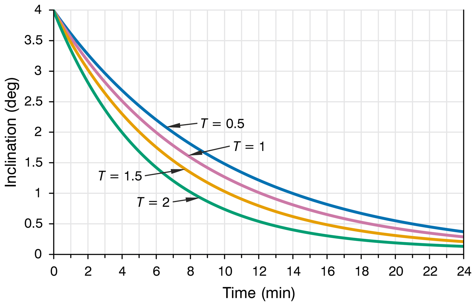
Drilling of Borehole 1 with T = 0.5 was unsuccessful owing to water leakage from the borehole; consequently, the results were difficult to analyze. The graph illustrates an approximation option intended to be obtained based on the analysis of the other three experiments. The experiment demonstrates that the correction coefficient T affected how rapidly the borehole deviation changed over time. For clarity, the approximations of all four experiments are shown in Fig. 17.
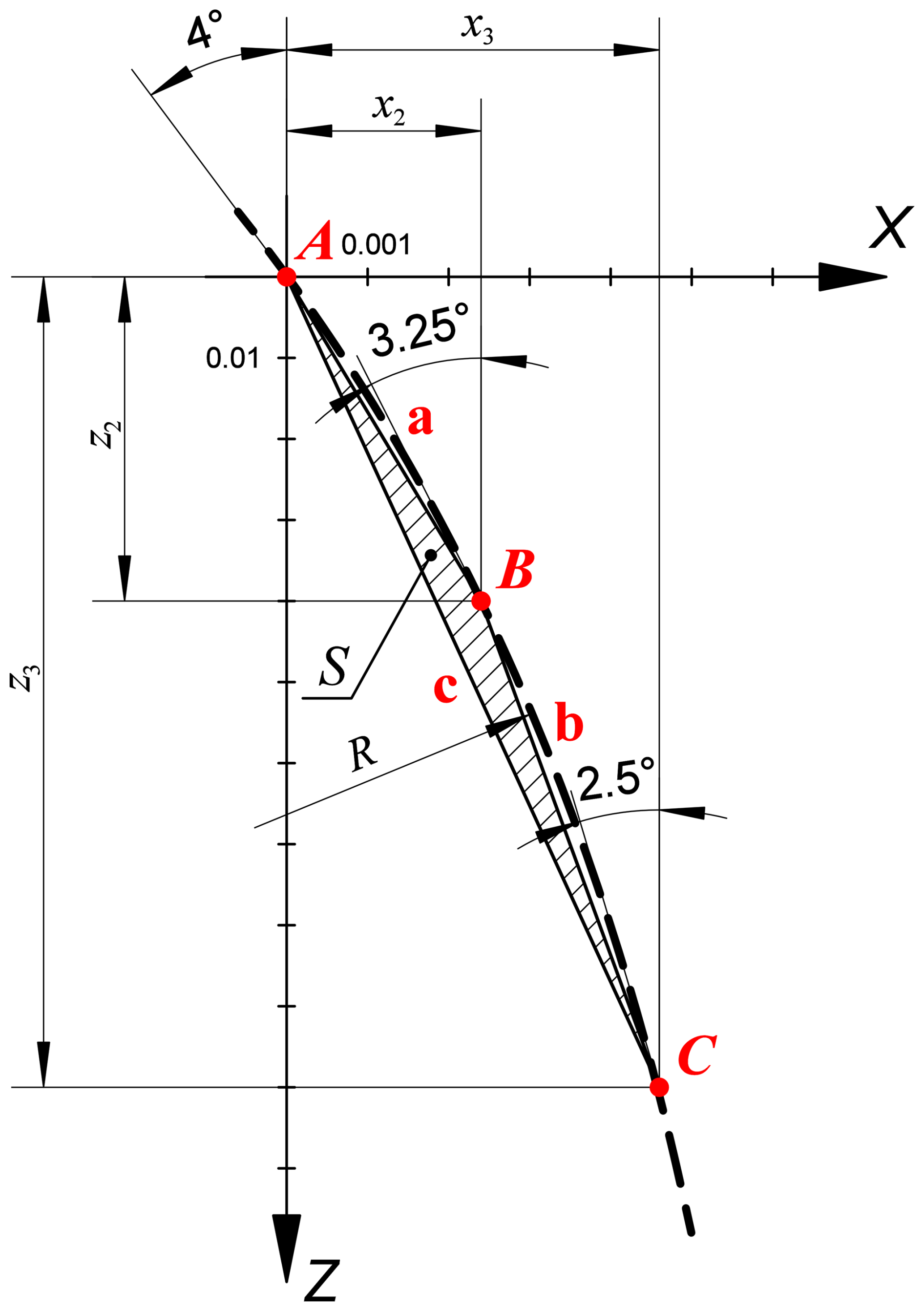
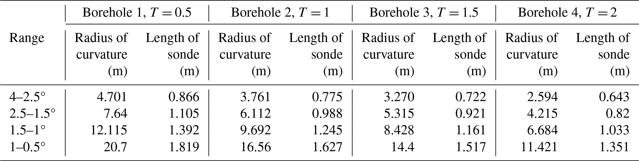
Table 8Radius of curvature and maximum allowable sonde length.
To understand how crucial borehole deviations are for the passability of the sonde prototype, it is necessary to analyze the results for the allowable deviation intensity according to the method described in Sect. 3. In the experiments, the automatic alignment length was approximately 0.5 m. For clarity, it was decided to divide this 0.5 m section of each borehole into several sections, for each of which the radius of curvature was determined. The option of partitioning the path not according to depth but rather according to inclination angle proved to be the most illustrative. Four sections were selected with the following inclination angle ranges: 4–2.5°, 2.5–1.5°, 1.5–1°, and 1–0.5°.
The radius of curvature was determined for all four boreholes in each of the selected sections. To determine the radius, an additional angle (approximately in the middle of the range) was selected. The following additional angle values were selected for further calculations: 3.25° for the range 4–2.5°, 2° for 2.5–1.5°, 1.25° for 1.5–1°, and 0.75° for 1–0.5°. Figure 18 shows the sonde trajectory for the 4–2.5° range in Borehole 2 (T = 1).
The sectional radius of curvature was calculated as follows:
where a, b, and c are the side lengths of triangle ABC and S is the area of triangle ABC.
The area of the triangle can be determined using Heron's equation:
where p is the semi-perimeter of a triangle.
The side lengths of triangle ABC can be determined using the Pythagorean theorem given that the coordinates of the points A (x1, z1), B (x2, z2), and C (x3, z3) are known.
Knowing the coordinates of points A, B, and C for all sections using Eqs. (12)–(16), the radius of curvature of each section can be determined. Substituting the radius of curvature into Eq. (6), the maximum allowable sonde length satisfying the passability criteria for each segment can be determined. The resulting radius of curvature and maximum allowable sonde length values are presented in Table 8 and Fig. 19.
It is worth noting that the difference between the initial and final angles has a significant impact on the radius of curvature. If the analyzed section tends to zero, the radius of curvature of such a section tends to infinity, and vice versa. As a compromise, the ranges were selected to minimize the difference between the size of the deviation angle ranges and the corresponding borehole section lengths.
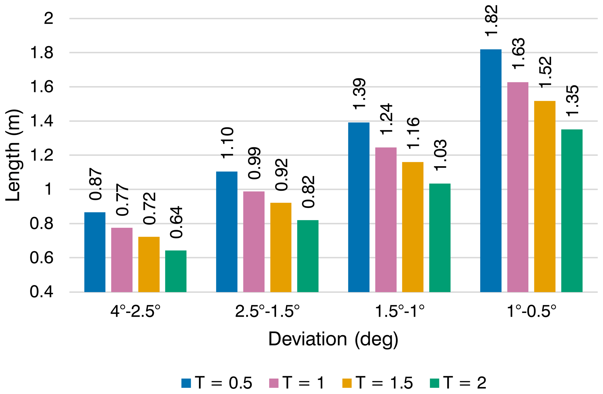
Figure 19Dependence of the maximum allowable sonde length at different borehole sections with the same inclination change.
Based on the experimental results for the sonde prototype, the main conclusions of this study can be summarized as follows.
-
The sonde prototype demonstrates promising potential in controlling the borehole direction, and using the RECAS, it should be possible to control the borehole direction to a certain extent using the proposed method.
-
The borehole deviation intensity during drilling can be corrected by controlling the correction coefficient T.
-
It is worth noting that the radius of curvature of a real RECAS would be higher than that obtained experimentally. Further research is required to obtain the RECAS parameters. However, to prevent the RECAS from becoming stuck in its own borehole at the chosen experimental drilling parameters, the borehole deviation radius intensity must be reduced.
-
At the maximum borehole diameter value obtained in the field for the RECAS-200 prototype, the maximum theoretical borehole deviation value cannot exceed 0.67° at a sonde length of approximately 7 m. However, this calculation did not consider the fact that a 7 m long sonde may exhibit some deformability (especially at the joints), despite its housing being made of stainless steel. At this length, even a small deformation of a few millimeters could positively affect the passability of the sonde in the borehole.
-
Sonde passability at large borehole deviation intensity values can be improved if the housing is structurally divided into several parts capable of deviating from each other (hinged joints). Allowing just a half-degree deviation of one part of the sonde from the other could increase its passability.
In future work, we plan to conduct experiments on a larger scale (e.g., with a borehole depth of approximately 10 m) to refine the results in a deviation intensity range closer to that obtained with a real RECAS.
All raw data can be provided by the corresponding authors upon request.
The supplement related to this article is available online at https://doi.org/10.5194/gi-14-29-2025-supplement.
Conceptualization: TPG, SMA, FX; hardware and equipment design: SMA, GD; software development: SMA; resources and supplies: FX, GD, DZ, ZN; planning the experiment: SMA, TPG; assistance in preparing for experiments: FX, ZN, GD, DZ; conducting experiments and performed the measurements: SMA, FX; analyzing the data: SMA, TPG; project administration: FX, ZN; financial management: YY, WT; supervision: TPG; writing the manuscript draft: SMA, TPG; reviewing and editing the manuscript: TPG; reviewing the manuscript: FX, GD.
The contact author has declared that none of the authors has any competing interests.
Publisher's note: Copernicus Publications remains neutral with regard to jurisdictional claims made in the text, published maps, institutional affiliations, or any other geographical representation in this paper. While Copernicus Publications makes every effort to include appropriate place names, the final responsibility lies with the authors.
We thank all teachers, engineers, and postgraduate students at the Polar Research Center of Jilin University for their hard work in developing and testing the thermal sonde and solving various problems. We also thank the members of the FagearTechCorner discord server community for their help in development and fruitful suggestions.
This research has been supported by the National Key Research and Development Project of the Ministry of Science and Technology of China (grants nos. 2023YFC2812602, 2021YFC2801401) and the National Natural Science Foundation of China (grant no. 41941005).
This paper was edited by Lev Eppelbaum and reviewed by five anonymous referees.
Ashmore, D. W. and Bingham, R. G.: Antarctic subglacial hydrology: current knowledge and future challenges, Antartic Sci., 26, 758–773, https://doi.org/10.1017/S0954102014000546, 2014.
Bowling, J. S., Livingstone, S. J., Sole, A. J., and Chu, W.: Distribution and dynamics of Greenland subglacial lakes, Nat. Commun., 10, 2810, https://doi.org/10.1038/s41467-019-10821-w, 2019.
Dachwald, B., Mikucki, J., Tulaczyk, S., Digel, I., Espe, C., Feldmann, M., Francke, G., Kowalski, J., and Xu, C.: IceMole: a maneuverable probe for clean in situ analysis and sampling of subsurface ice and subglacial aquatic ecosystems, Ann. Glaciol., 55, 14–22, https://doi.org/10.3189/2014AoG65A004, 2014.
Heinen, D., Audehm, J., Becker, F., Boeck, G., Espe, C., Feldmann, M., Francke, G., Friend, P., Haberberger, N., Helbin, K., Nghe, C. T., Stelzig, M., Vossiek, M., Wiebusch, C., and Zierke, S.: The TRIPLE Melting Probe – an Electro-Thermal Drill with a Forefield Reconnaissance System to Access Subglacial Lakes and Oceans, in: OCEANS 2021: San Diego–Porto, 20–23 September 2021, San Diego, CA, USA, https://doi.org/10.23919/OCEANS44145.2021.9705999, 1–7, 2021.
Kyurkchiev, N. and Markov, S.: Sigmoid Functions: Some Approximation and Modelling Aspects Some Moduli in Programming Environment MATHEMATICA, 1. edn., LAP LAMBERT Academic Publishing, Saarbrücken, 2015, ISBN: 978-3-659-76045-7, 2015.
Li, X.: Research on the temperature field and closure rate of ice hole formed by thermal drill, Dissertation for the Doctoral Degree, Jilin University, Changchun, 2020.
Li, Y., Talalay, P. G., Sysoev, M. A., Zagorodnov, V. S., Li, X., and Fan, X.: Thermal Heads for Melt Drilling to Subglacial Lakes: Design and Testing, Astrobiology, 20, 142–156, https://doi.org/10.1089/ast.2019.2103, 2020.
Livingstone, S. J., Li, Y., Rutishauser, A., Sanderson, R. J., Winter, K., Mikucki, J. A., Björnsson, H., Bowling, J. S., Chu, W., Dow, C. F., Fricker, H. A., McMillan, M., Ng, F. S. L., Ross, N., Siegert, M. J., Siegfried, M., and Sole, A. J.: Subglacial lakes and their changing role in a warming climate, Nat. Rev. Earth. Environ., 3, 106–124, https://doi.org/10.1038/s43017-021-00246-9, 2022.
Pereira, P. V., Durka, M. J., Hogan, B. P., Richmond, K., Smith, M. W. E., Winebrenner, D. P., Elam, W. T., Hockman, B. J., Lopez, A., Tanner, N., Moor, J., Ralston, J., Alexander, M., Zimmerman, W., Flannery, N., Kuhl, W., Wielgosz, S., Cahoy, K. L., Cwik, T. A., and Stone, W. C.: Experimental Validation of Cryobot Thermal Models for the Exploration of Ocean Worlds, Planet. Sci. J., 4, 81, https://doi.org/10.3847/PSJ/acc2b7, 2023.
Priscu, J. C., Kalin, J., Winans, J., Campbell, T., Siegfried, M. R., Skidmore, M., Dore, J. E., Leventer, A., Harwood, D. M., Duling, D., Zook, R., Burnett, J., Gibson, D., Krula, E., Mironov, A., McManis, J., Roberts, G., Rosenheim, B. E., Christner, B. C., Kasic, K., Fricker, H. A., Lyons, W. B., Barker, J., Bowling, M., Collins, B., Davis, C., Gagnon, A., Gardner, C., Gustafson, C., Kim, O.-S., Li, W., Michaud, A., Patterson, M. O., Tranter, M., Venturelli, R., Vick-Majors, T., Elsworth, C., and The SALSA Science Team: Scientific access into Mercer Subglacial Lake: scientific objectives, drilling operations and initial observations, Ann. Glaciol., 62, 340–352, https://doi.org/10.1017/aog.2021.10, 2021.
Schuler, C. G., Winebrenner, D. P., Elam, W. T., Burnett, J., Boles, B. W., and Mikucki, J. A.: In situ contamination of melt probes: implications for future subglacial microbiological sampling and icy worlds life detection missions, Geol. Soc. Am., 50, 312–314, https://doi.org/10.1130/abs/2018SE-312314, 2018.
Shamshev, F. A., Tarakanov, C. N., Kudrjashov, B. B., Parijskij, J. M., and Jakovlev, A. M.: Tehnologija i tehnika razvedochnogo burenija [Technology and technique of exploration drilling], Nedra, Moscow, UDC number: UDC 622.143(075), 1983 (in Russian).
Siegert, M. J., Woodward, J., and Royston-Bishop, G.: Antarctic Subglacial Lakes, in: Encyclopedia of Lakes and Reservoirs, edited by: Bengtsson, L., Herschy, R. W., and Fairbridge, R. W., Springer Netherlands, Dordrecht, https://doi.org/10.1007/978-1-4020-4410-6_39, 37–39, 2012a.
Siegert, M. J., Clarke, R. J., Mowlem, M., Ross, N., Hill, C. S., Tait, A., Hodgson, D., Parnell, J., Tranter, M., Pearce, D., Bentley, M. J., Cockell, C., Tsaloglou, M., Smith, A., Woodward, J., Brito, M. P., and Waugh, E.: Clean access, measurement, and sampling of Ellsworth Subglacial Lake: A method for exploring deep Antarctic subglacial lake environments, Rev. Geophys., 50, 2011RG000361, https://doi.org/10.1029/2011RG000361, 2012b.
Skidmore, M.: Microbial communities in Antarctic subglacial aquatic environments, in: Geophysical Monograph Series, vol. 192, edited by: Siegert, M. J., Kennicutt, M. C., and Bindschadler, R. A., American Geophysical Union, Washington, DC, https://doi.org/10.1029/2010GM000995, 61–81, 2011.
Stone, W., Hogan, B., Siegel, V., Harman, J., Flesher, C., Clark, E., Pradhan, O., Gasiewski, A., Howe, S., and Howe, T.: Project VALKYRIE: Laser-Powered Cryobots and Other Methods for Penetrating Deep Ice on Ocean Worlds, in: Outer Solar System, edited by: Badescu, V. and Zacny, K., Springer International Publishing, Cham, https://doi.org/10.1007/978-3-319-73845-1_4, 47–165, 2018.
Sun, Y., Li, B., Fan, X., Li, Y., Li, G., Yu, H., Li, H., Wang, D., Zhang, N., Gong, D., Wang, R., Li, Y., and Talalay, P. G.: Brief communication: New sonde to unravel the mystery of polar subglacial lakes, The Cryosphere, 17, 1089–1095, https://doi.org/10.5194/tc-17-1089-2023, 2023.
Sun, Y., Pavel, T., Li, Y., Yu, H., Wang, D., Li, G., Xu, L., Gong, D., Wang, J., Wang, J., Wang, T., Zhang, N., Wang, Z., Chen, Y., Liu, Y., Li, Y., Peng, S., Shi, J., An, C., Ge, Q., Xu, J., Ni, X., Cui, Q., Jiang, Q., Mikhail, S., Yang, Y., Wang, R., Wei, X., Wang, Y., Zhu, T., Deng, Z., Alexey, M., Li, B., and Fan, X.: Exploring Antarctic subglacial lakes with RECoverable Autonomous Sonde (RECAS): Design and first field tests, Sci. China Technol. Sc., 67, 1866–1878, https://doi.org/10.1007/s11431-023-2620-3, 2024.
Talalay, P. G., Zagorodnov, V. S., Markov, A. N., Sysoev, M. A., and Hong, J.: Recoverable autonomous sonde (RECAS) for environmental exploration of Antarctic subglacial lakes: general concept, Ann. Glaciol., 55, 23–30, https://doi.org/10.3189/2014AoG65A003, 2014.
Talalay, P. G., Li, Y., Sysoev, M. A., Hong, J., Li, X., and Fan, X.: Thermal tips for ice hot-point drilling: Experiments and preliminary thermal modeling, Cold Reg. Sci. Technol., 160, 97–109, https://doi.org/10.1016/j.coldregions.2019.01.015, 2019.
Tulaczyk, S., Mikucki, J. A., Siegfried, M. R., Priscu, J. C., Barcheck, C. G., Beem, L. H., Behar, A., Burnett, J., Christner, B. C., Fisher, A. T., Fricker, H. A., Mankoff, K. D., Powell, R. D., Rack, F., Sampson, D., Scherer, R. P., Schwartz, S. Y., and The Wissard Science Team: WISSARD at Subglacial Lake Whillans, West Antarctica: scientific operations and initial observations, Ann. Glaciol., 55, 51–58, https://doi.org/10.3189/2014AoG65A009, 2014.
Wright, A. and Siegert, M. J.: The identification and physiographical setting of Antarctic subglacial lakes: An update based on recent discoveries, in: Geophysical Monograph Series, Vol. 192, edited by: Siegert, M. J., Kennicutt, M. C., and Bindschadler, R. A., American Geophysical Union, Washington, DC, 9–26 pp., https://doi.org/10.1029/2010GM000933, 2011.
Ye, Y., Zierke, S., Li, B., Heinen, D., Li, Y., Wiebusch, C., Kaiser, S., Sun, Y., and Fan, X.: Melting trajectory of the asymmetrically-heated conical thermal head for ice-melting probes, Case Stud. Thermal Eng., 55, 104160, https://doi.org/10.1016/j.csite.2024.104160, 2024.
Zvarygin, V. I.: Burovye stanki i burenie skvazhin [Drilling rigs and well drilling], Siberian Federal University, Krasnoyarsk, ISBN 978-5-7638-2219-9, 2011 (in Russian).
- Abstract
- Introduction
- Steering approaches of the RECAS
- Passability of the RECAS
- Testing stand and sonde prototype design
- Laboratory testing of the self-steering sonde prototype
- Conclusions
- Data availability
- Author contributions
- Competing interests
- Disclaimer
- Acknowledgements
- Financial support
- Review statement
- References
- Supplement