the Creative Commons Attribution 4.0 License.
the Creative Commons Attribution 4.0 License.
Development of high-precision distributed wireless microseismic acquisition stations
Shuaiqing Qiao
Hongmei Duan
Qisheng Zhang
Qimao Zhang
Shuhan Li
Shenghui Liu
Shiyang Liu
Yongqing Wang
Shichu Yan
Wenhao Li
Feng Guo
In recent years, owing to the shortage of oil and gas resources and increasing difficulty in mining, traditional (wired) microseismic monitoring equipment has been unable to meet the needs of energy exploitation. Therefore, it is necessary to develop new high-precision seismic exploration and data acquisition systems. In this study, we combined advanced acquisition systems with wireless technology to develop a new wireless microseismic acquisition system. The hardware circuit of the acquisition system mainly includes a data acquisition board and a main control board. High-precision analog-to-digital conversion and digital filtering technologies are used to provide data with high signal-to-noise ratios, resolution, and fidelity to the acquisition stations. Key technologies were integrated into the ARM (Advanced RISC Machines) of the main control board: reliable GPS technology was employed to realize synchronous acquisitions among various acquisition stations, and WIFI technology was used to achieve wireless data communication between acquisition stations and the central station, thus improving the data transmission speed and accuracy. After conducting a series of evaluation tests, it was found that the system was stable, convenient to use, and had high data accuracy, therefore providing significant support for the solution to problems encountered in current oil and gas exploration processes, such as the complicated environment and inconvenient construction.
- Article
(2114 KB) - Full-text XML
- BibTeX
- EndNote
From a global view point, 50 % dependence on imported petroleum can be regarded as a economic security warning. However, in 2017, China's foreign dependence exceeded 67.4 %, which poses a threat to the energy and economic security of the country (Mazza et al., 2012; CNPC Research Institute of Economics and Technology, 2017). Therefore, the exploration of domestic oil and gas resources in China should be enhanced to contribute to the stability and sustainable development of the country, and also to build a more prosperous society (Wood and Gettrust, 2002). With the development of oil and gas exploration technologies, China has entered the difficult stage of oil and gas exploration, namely the exploration of the pre-Cenozoic marine residual basin (Wu et al., 2011). This involves the search for oil and gas resources in complex geological areas, such as buried hills and their internal structures, and geological formations on high and steep hillsides. In addition to the increase in depth of detection, surface and underground conditions will become more complex. Consequently, there will be new requirements and challenges for seismographs, therefore resulting in an urgent need to develop a novel high-accuracy seismic data acquisition system suitable for China's conditions (Li and Liu, 2013). In recent years, as the country has placed more emphasis on the research and development of geophysical instruments, the number of research units engaged in studies on seismic data acquisition and recording systems has continuously increased.
The most powerful and widely used geophysical method for oil and gas exploration is reflection seismology (Morandi and Ceragioli, 2002). As the main equipment for seismic exploration, the acquisition station is the core of resource exploration and energy acquisition, with the collection of raw data with high signal-to-noise ratio (SNR), resolution, and fidelity being the most crucial aspects (Mazza et al., 2012; Mrmureanu and Ionescu, 2011). A distributed wireless microseismic acquisition station preprocesses and amplifies the analog signals collected by the detector and converts them into digital signals with a strong anti-interference ability. The development of seismic instruments has relied heavily on the continuous development of seismic data acquisition methods. Since the advent of digital computers over half a century ago, people have increasingly emphasized the use of numbers to accurately quantify various physical quantities and to transfer information. As a result, digital technologies have been developed in many fields, thus driving the rapid development of microelectronics and computer technologies. Digitization has been proposed in geophysical exploration since the 1960s, with digital seismographs being one of the first examples (Guo and Liu, 2009). A renowned electronic device manufacturer in the USA, Texas Instruments (TI), developed the DFSIV and DFSV digital seismographs. The French manufacturer SERCEL also introduced the SN328 and SN338 digital seismographs, which used seven-stage instantaneous floating-point amplifiers (Huang and Yu, 1994).
The design concept of the centralized instruments DFSV and SN338 limited the increase in channel numbers, and the traveling distances of the seismic wave analog signals sensed by the detectors along the bulky common depth point (CDP) cables were also too long, exceeding 3 km in some cases. In addition, the distance of signal transmission along the cable varied among different channels, and the signals were severely adulterated by induction (Huang and Yu, 1994). The SN388, 408UL, 428XL, and 508XT systems subsequently introduced by SERCEL offered enhanced processing power, integration level, and stability, but still had shortcomings in terms of gain, cost, and human–machine interaction (Liu, 2015).
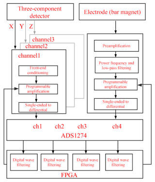
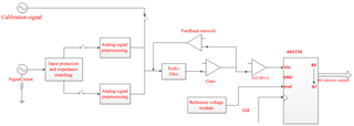
Figure 1Structural block diagram of the hybrid acquisition system based on the ADS1274 high-precision seismic electrical method.
With the dramatic increase in the number of seismic acquisition channels and exploration in remote regions, the production efficiency of cable systems has been reduced. In regions that are difficult to access and where the environment is vulnerable, cable systems should be supplemented or replaced by wireless systems. At present, the goal of seismograph research and development is to establish high-resolution, high-precision, and synchronous data acquisition, as well as real-time, high-speed, and low-power data transmission (Zhang et al., 2013). Therefore, the development of a new wireless microseismic digital acquisition system on the basis of traditional seismic instruments is of great significance.
2.1 Acquisition circuit design
The acquisition board is the front-end circuit of the main control board and is responsible for processing the analog electrical signals collected by detectors (or electrodes) and converting them into digital signals to be processed. Figure 1 shows the structural block diagram of the simulation board of the acquisition station.
The front end of the three channels of the ADS1274 analog-to-digital converter (ADC) is connected to a three-component seismometer, and can simultaneously acquire the X, Y, and Z components of the seismic wave. Three analog signals (the seismic wave signal in the X, Y, and Z directions) input by the detector are first filtered and denoised by the front-end conditioning circuit. Next, the signals are amplified by the programmable amplifier and further filtered by a single-ended differential circuit. They are then converted into a differential signal, input to the ADS1274 for analog-to-digital (AD) conversion, and finally passed to the field programmable gate array (FPGA) circuit for digital filtering.
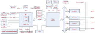
Figure 4Block diagram of the hardware design for the main control circuit of the wireless microseismic acquisition station.
The front end of the other channel of the ADS1274 is connected to an electrode (or magnetic bar). The analog signal input by the electrode is amplified by a preamplifier circuit and passes through a filter to eliminate unwanted signals in order to improve the SNR. The filtered analog input signal is further amplified by the main amplifier circuit, which is controlled by the FPGA, and passes through the ADS1274 to be converted into a digital signal. The digital signal is then fed to the FPGA for digitalization.
Figure 2 shows the operational block diagram of the single channel of the acquisition board design. The AD conversion chip used in this design is the 24 bit ADS1274 manufactured by TI. The chip has four acquisition channels that can acquire data simultaneously. The first three channels are used to collect seismic signals in three directions (X, Y, and Z components), while the fourth channel is used to acquire electrical signals. The processing steps are similar for the four analog channels.
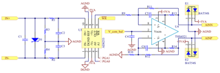
Figure 3 is the schematic diagram of the single channel of the acquisition board. The signal first enters the acquisition board through the input protection and impedance-matching circuit. The front-end conditioning circuit preprocesses the analog signal to reduce waveform distortion, and the preprocessed signal is filtered using a low-pass filter to remove the high-frequency clutter signals brought in from the detector. The filtered signal is then subsequently amplified. In this design, a programmable gain amplifier AD8253 is used. Through the IO port, the CPU can control its gain to 0, 20, 40, or 60 dB so that the gain can be controlled according to the input signal size in order to achieve a higher resolution for the acquisition board. The amplified signal passes through the AD driver chip so that the single-ended signal is converted into a differential signal (that is, the input to the ADS1274 is a differential signal). The differential signal is then input to the ADS1274 for AD conversion, and the digital signal is output by the AD chip.
The calibration signal in the schematic diagram is generated by an analog switch chip. The IO port of the FPGA can control the switching frequency of the chip to generate square waves with different frequencies, which can be used to perform self-testing on the acquisition system. The reference voltage module REF5025 generates a 2.5 V standard reference voltage for the AD chip. The clock of the AD chip (CLK) is generated from the FPGA module on the main control board.
2.2 Acquisition station master control circuit design
Figure 4 is a diagram of the hardware design for the main control circuit of the wireless microseismic acquisition station. The embedded control software in the seismic data acquisition system runs on the main control circuit, which is the core of the distributed wireless microseismic acquisition station. The OMAP3730 processor and the Linux 2.6.37 operating system are adopted in the core control processor. OMAP3730 is a dual-core processor integrating ARM (Advanced RISC Machines) and DSP (digital signal processing) processors, and can perform signal acquisition control and real-time data storage. The embedded operating system Linux 2.6.37 runs on the processor and is responsible for task scheduling. A high-speed memory management controller chip is used as the data storage medium, while power-up management, power supply management, LED driving, and keypad management are performed through the general-purpose input/output (GPIO) port of the OMAP3730 processor. The FPGA section is used to accomplish multiple tasks that cannot be performed by general-purpose processors; these are (1) control of scheduling and execution of all time-related tasks, including the generation of the sampling and real-time clocks, scheduling of related strategies, etc.; (2) acquisition and control of voltage, current, temperature, and other sensor data; (3) acquisition system control and data buffering; (4) wired data communication; and (5) decoding and time synchronization of GPS information.
The main control board is the core control processing unit of the acquisition station. The design combines the high-performance industrial-grade control system board OMAP3730 and the XC3S2000 FPGA to achieve the following functions.
-
system monitoring function: monitoring of power supply voltage, electric current, system temperature, and other boards
-
communication management: USB and serial communications
-
data storage function: storage in SDHC card
-
acquisition system control and configuration, and data processing functions
-
time scheduling management functions: synchronization of real-time clock and GPS time, with FPGA being responsible for time-based scheduling control management
-
control of human–computer interaction board
-
storage status indication function
-
communication status indication function
-
data preprocessing function
-
other auxiliary functions
The OMAP3730 core control system board circuit integrates the general-purpose memory controller (GPMC) bus, SD card, serial communication, USB, GPIO, and other functional interfaces to simplify the system design. As one USB interface integrated in the OMAP3730 core control system cannot meet the system implementation requirements, we decided to expand the USB interface to communicate with the WIFI module. A high-speed USB 2.0 PHY chip, USB 3320, was used, and the industrial-grade SDIO (secure digital input and output) wireless module RS9110 was used for the WIFI module. RS9110 is a WIFI module that supports 802.11n b g−1 and has high-performance wireless transmission capabilities. The clock module provides the acquisition system with accurate clock frequencies, GPS, and other information. The clock module communicates with the master-control FPGA through UART (universal asynchronous receiver/transmitter) and SPI (serial peripheral interface). The master-control FPGA reads the GPS status information through UART and calculates and adjusts the digital-to-analog output voltage through the continuous count of pulses per second (PPS), so that the frequency of the constant-temperature crystal oscillator is more accurate.
3.1 Summary of software requirement
The software designed in this study adopts the traditional software development life cycle method, and also the top-down and stepwise refinement structural software design approach.
The main functions to be achieved by the software are as follows: disk management, equipment calibration, CRC data verification, data acquisition and storage, real-time data transmission over the network, peripheral acquisition equipment management, GPS information analysis, keypad management, LED status management, wireless network configuration, and large-line network management.
3.2 Software architecture of the distributed wireless microseismic acquisition station
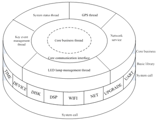
The embedded control software runs on the Linux 2.6.37 system platform. The primary library of the system provides a basic platform for device hardware control functions. Regardless of whether the users are in threads or processes, any user can directly call the system-related interface functions to perform the corresponding tasks. The primary library mainly includes the following: time management interfaces, device management interfaces, disk management interfaces, wireless network management interfaces, network management interfaces, upgrade interfaces, and serial port management interfaces. System calls are an important part of the system and depend on the underlying operating system and the GNU C Library.
The core business layer consists of five submodules and a main task as shown in Fig. 5, with each component being a separate thread.
-
main thread: responsible for the data acquisition, instrument calibration, and data deletion processes;
-
system status thread: responsible for monitoring the system status, including disk capacity, voltage, current, temperature, synchronization status, etc., and handling of response status;
-
GPS decoding thread: responsible for decoding GPS information;
-
network communication thread: includes communication with notebooks through wireless network management and communication with large-line transmission systems through large-line network management;
-
key event management thread: receives the user's key operations and takes corresponding action according to the operations;
-
LED lamp management thread: indicates the current status of the system through different statuses of the LED lamp.
The core communication interface module is an interface for communication between different threads to establish a message communication mechanism among threads.
Under the core business layer, the system management module for the electromagnetic data acquisition system mainly includes a time management module, a device driver module, a disk management module, wireless network configuration, and serial port configuration.
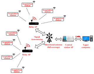
The field work mode of the distributed wireless acquisition system is shown in Fig. 6. A relay access point (AP) is placed in a certain area as a relay point to connect with a certain number of wireless seismic acquisition stations for wireless data transmission. Multiple relay APs are used to cover all wireless acquisition stations in the construction area. The central station AP connects with each relay AP through the omnidirectional coverage antenna to issue commands and collect real-time data.
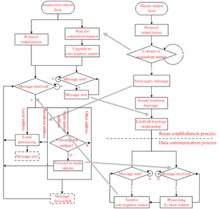
The communication and interaction process of the wireless network is shown in Fig. 7.
5.1 Noise test
The equivalent input noise refers to the output of the seismic acquisition station when the input end of the station is connected to the standard resistance. The measurement result is converted into the root mean square (RMS) voltage value, usually expressed in microvolts. The equivalent input noise is mainly composed of ADC quantization noise and the thermal noise of the components, and is directly superimposed on the input seismic signal during operation. Therefore, it determines the capability of the instrument to distinguish weak signals, wherein lower equivalent input noise is more desirable.
When the equivalent input noise is tested, the analog signal input terminal must be connected with a terminal test resistor. In the present design, a resistor of 1 kΩ resistance was used. During the test, the sampling rate of the ADS1274 was set to 1000 SPS (samples per second), and data corresponding to preamp gains of ×1, ×10, ×100, and ×1000 were respectively collected. Data from 8192 sample points were collected for processing and analysis.
The calculation method in the equivalent input noise test is as follows. First, the average value of amplitude Xi for N samples was calculated using Eq. (1) to obtain the DC offset (dc) of the noise signal.
Next, the RMS after drift removal, which is the equivalent input noise of the instrument, was then calculated as
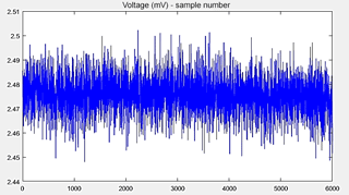
Then, by analyzing the data of 8192 sampling points, the equivalent input noise waveform was plotted, as shown in Fig. 8.
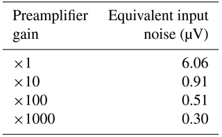
Table 1 presents the equivalent noise output results of the preprogrammed amplifier with different gains. According to the obtained results from the processed data, it can be seen that when the amplification of the programmable amplifier was 40 dB, the equivalent input noise of the acquisition station was 0.51 µV (approximately 0.5 µV). Therefore, it can be concluded that the acquisition accuracy of the acquisition station satisfied the expected requirements.
5.2 Harmonic distortion test
Harmonic distortion refers to the nonlinear distortion of the output of a seismic instrument when a sinusoidal signal is inputted. It is usually measured by the ratio of the amplitude of each harmonic component to the RMS of the fundamental signal amplitude. The harmonic distortion of the seismograph reflects the fidelity of the seismic instrument in the acquisition and recording of seismic signals. This indicator is closely related to the noise and instantaneous dynamic range of the instrument. If the harmonic distortion of the instrument is excessively large, each harmonic component of the seismic signal will be converted into noise, thus reducing the dynamic range of the system. At the same time, if the harmonic distortion of the instrument is excessively large, the high-order harmonics generated by the low-frequency surface waves with strong amplitude are likely to be mixed into the frequency band of the low-amplitude effective signal, thereby causing interference. The harmonic distortion of seismic instruments is therefore an important performance indicator.
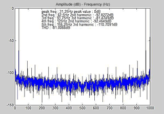
Discrete Fourier transform (DFT) of length N was performed on the signal sequence x(n) to obtain the discrete frequency spectrum X(k), and to find the maximum spectral magnitude point . The corresponding discrete frequency point p in the spectrum diagram is the corresponding frequency point of the fundamental wave. Assuming that each harmonic amplitude is Ai, the harmonic distortion (THD) was computed using Eq. (3), and the fifth harmonic was obtained in the actual calculation.
When the data length is a non-integer multiple of the period of the sine wave, the energy of the fundamental wave and the harmonic wave will leak into the adjacent frequency band, thus resulting in spectral leakage. In the actual calculation of harmonic distortion, direct use of DFT for spectral analysis often causes frequency spectrum leakage, so that the calculated spectrum does not accurately reflect the frequency characteristics of the signal. Therefore, it is usually necessary to perform window processing on the measured signal, with a minimum energy window being most optimum.
The test result is shown in Fig. 9.
5.3 Synchronization test of acquisition stations
In seismic exploration experiments, the precise collection of seismic wave signals and the recording of their corresponding travel time are extremely important. This requires data to be acquired synchronously by each sensor (Mougenot, 2013).
In the present design, GPS technology is the key to accomplishing synchronous acquisition. The LEA-6T timing receiver, which can output PPS signals with a precision of up to 15 ns, has been adopted in this design. At the same time, it has dedicated frequency and PPS output pins, with a precision as high as 10−12.
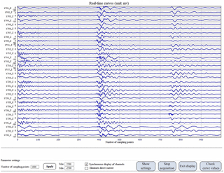
During the test, acquisition was conducted on 32 acquisition stations simultaneously. Figure 10 shows the acquisition of 32 stations under the same seismic source. As seen from the figure, when vibrations were emitted from the source, the entire 32 acquisition stations collected data almost simultaneously, which indicates good synchronization performance between them. After the actual measurement and calculation, the synchronization accuracy of the acquisition station is measured to reach 100 ns.
5.4 Acquisition station performance comparison
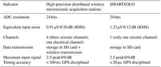
After the performance test of the acquisition station was completed, the wireless microseismic acquisition station was compared with a new type of seismic acquisition station on the market. The selected acquisition station was the intelligent acquisition station displayed by the Italian DTCC/SmartSolo® at CPS/SEG 2018 in Beijing, 24–27 April. Six aspects including equivalent input noise, timing accuracy, and data transmission were compared. These reflect the superiority of high-precision distributed wireless microseismic acquisition stations in some aspects. Table 2 shows the specific performance comparison results.
In this study, a high-precision distributed wireless microseismic acquisition system has been designed for oil and gas exploration. The system design, which was based on the ADS1274 chip manufactured by TI, made full use of the four channels of the chip to collect vibration signals in three directions and one electrical signal. Furthermore, the acquisition system uses GPS and WIFI technologies to achieve distributed wireless acquisition. After single-station testing and multi-station joint testing of the acquisition stations, the results show that the system's performance in equivalent noise, harmonic distortion testing, and synchronous acquisition was able to meet the expected requirements. As such, the acquisition system is currently being practically applied in production operations.
There are no publicly available data for this study.
The author worked as the hardware design and post-debugging throughout the development process, as well as the drafting of the manuscript.
The authors declare that they have no conflict of interest.
This work was supported by the Natural Science Foundation of China
(no. 41574131), the National Key Research and Development Program of China
(no. 2017YFF0105704), the National “863” Program of China (no. 2012AA06110203),
and the Fundamental Research Funds for the Central
Universities of China.
Edited by: Lev Eppelbaum
Reviewed by: Chen Guangyuan and one anonymous referee
CNPC Research Institute of Economics and Technology: Report of Developments in Domestic and Foreign Oil and Gas Industries, Petroleum Business News, 2017.
Guo, J. and Liu, G.-D.: Current situation and expectation of cable-less seismic acquisition system, Prog. Geophys., 5, 1540–1549, 2009.
Huang, X.-L. and Yu, J.-S.:Numerical analysis for the characteristics of SN338 digital seismic instrument, Chinese J. Geophys.-Ch., 37, 597–602, 1994.
Li, H.-L. and Liu, M.-Z.: Key techniques of wireless telemetry digital seismograph, Chinese J. Geophys.-Ch., 56, 3673–3682, 2013.
Liu, B.: Analysis of the differences between several SERCEL devices, Science & Technology Information, 13, 209–209, 2015.
Mazza, S., Basili, A., Bono, A., Lauciani, V., Mandiello, A. G., Marcocci, C., Mele, F., Pintore, S., Quintiliani, M., Scognamiglio, L., and Selvaggi, G.: AIDA–Seismic data acquisition, processing, storage and distribution at the National Earthquake Center, INGV, Ann. Geophys., 55, 541–548, 2012.
Morandi, S. and Ceragioli, E.: Integrated interpretation of seismic and resistivity images across the “Val d'Agri” graben (Italy), Ann. Geophys., 45, 259–271, 2002.
Mougenot, D.: SERCEL: Application of the UNITE system in real-time fracture monitoring, Petroleum and Equipment, 1, 38–41, 2013.
Mrmureanu, A., Ionescu, C., and Cioflan, C. O.: Advanced real-time acquisition of the Vrancea earthquake early warning system, Soil Dyn. Earthq. Eng., 31, 163–169, 2011.
Teng, J. W.: Ponder and research on the genesis and occurrence of strong earthquakes and the prediction of their place, time and intensity, Chinese J. Geophys.-Chi., 53, 1749–1766, 2010.
Wood, W. T. and Gettrust, J. F.: New developments in deep-towed seismic acquisition, IEEE Oceans Conference Record, 1139–1142, 2002.
Wu, Z.-Q., Wu, S.-G., Tong, S.-Y., Liu, H.-S., and Zhang, Y.-B.: A study on seismic acquisition basic on marine carbonate hydrocarbon exploration in the southern Yellow Sea, Chinese J. Geophys.-Ch., 54, 1061–1070, 2011.
Zhang, Q., Deng, M., Guo, J., Luo, W., Wang, Q., and Feng, Y.: Development of a new seismic-data acquisition station based on system-on-a-programmable-chip technology, Ann. Geophys., 56, 1–8, 2013.


