the Creative Commons Attribution 4.0 License.
the Creative Commons Attribution 4.0 License.
 | 13 Aug 2019
In situ calibration of offsetting magnetometer feedback transients on the Cassiope spacecraft
Andrew D. Howarth
Greg A. Enno
We present an in situ calibration process to derive the transient behavior of the offsetting fluxgate magnetometer (MGF) instruments on the Cassiope spacecraft. The dynamic behavior of the MGF changed on orbit following a software update. Characterizing the new instrument dynamics during normal spacecraft operations and then removing the transients was confounded by significant magnetic interference from the reaction wheels used to orient the spacecraft. Special operations were performed where data were taken in a safehold mode, with the reaction wheels stopped, following a single-event upset of the spacecraft bus flight computer after transiting the South Atlantic Anomaly. The slow single-axis rotation of the safehold mode was used to characterize the fluxgate's new feedback dynamics. This characterization process was then adapted for routine operation intervals with slow reaction wheel rates to allow the transient behavior to be characterized over long intervals of data spanning a wide range of temperatures. Subtracting these characterized transients from the flight data improves the instrument's noise floor and allows the instrument to accurately track rapidly changing local fields without loss of measurement fidelity. More generally, this characterization process should apply to other situations where the dynamics of an offsetting instrument must be calibrated in situ.
- Article
(3503 KB) - Full-text XML
- BibTeX
- EndNote


The Enhanced Polar Outflow Probe (e-POP) payload onboard the Cassiope spacecraft (Yau and James, 2015) includes the magnetic field instrument (MGF) to study small-scale field-aligned currents (Wallis et al., 2015). The MGF comprises two matched fluxgate magnetometers, referred to as inboard and outboard, deployed at different distances from the spacecraft on a common boom. The MGF uses an offsetting design, where digitally controlled magnetic feedback extends the magnetic range of the instrument allowing it to maintain fine (62.5 pT) resolution even in the strong ambient field at a perigee of ∼325 km. An MGF firmware patch to address a timing issue in the instrument was required after the launch of the spacecraft. This firmware patch, described below, changed the dynamics of the instrument as it updates its magnetic feedback to track the local field. Without appropriate compensation in post-processing, the magnetic feedback updates lead to non-physical transients on the order of 50 nT in the measured magnetic field. Two examples are highlighted in Fig. 1c by orange circles. The first is a <1 nT and results from a feedback step cross-coupled from another channel. The second is ∼50 nT (clipped by the y scale required to show the first transient) resulting from a feedback step on the same channel. Figure 1a shows how the processed magnetic field data can be contaminated with broadband noise, manifesting as vertical stripes in the dynamic spectra, resulting from the uncompensated transients after each update to the magnetic feedback used to null the magnetic field in the sensor (Fig. 1c). The varying intensity of the vertical stripes primarily relates to how often feedback is updated. Frequent updates aggregate to a higher power spectral density.

Figure 1Dynamic spectra of one instrument channel with (a) uncompensated transients and (b) compensated transients (cf. Figs. 5–7 below). These transients introduce bursts of broadband noise that manifest as vertical lines in the uncompensated spectra. The magnetic signatures of the spacecraft reaction wheels and their harmonics are visible near 17, 34, and 51 Hz and broaden during spacecraft maneuvers around 07:05 and 07:50 UTC. In the time domain (c, d) the reaction wheels create the visible enveloped sinusoidal signal. The broadband noise results from transients after updates to the instrument's magnetic feedback shown circled in panel (c) and compensated in panel (d). The time series in panels (c) and (d) correspond to the interval in the red dashed lines in panels (a) and (b). The orange circles show two uncompensated feedback transients – one <1 nT and one ∼50 nT.
The spacecraft maneuvers around 07:05 and 07:50 UTC, resulting in the visible spectral widening of the reaction wheel tones and their harmonics as the various wheel rates change. All components of the magnetometer experience rapid change as the spacecraft rotates, requiring many rapid updates to the digital feedback and resulting in the strong interference signal observed in the uncompensated spectra in Fig. 1a. Characterizing and correcting these transients, as described herein, significantly mitigates this effect resulting in the cleaner spectra shown as Fig. 1b.
Until now, these instrument transients have been mitigated by invalidating five samples after each update in post-processing and then restoring these values by interpolation. Unfortunately, during geophysically interesting intervals the local field can vary rapidly, necessitating frequent updates to the instrument's magnetic feedback and result in a high percentage of invalidated data. This can make the data interpolation poorly constrained as unaffected measurements of the magnetic field become sparse (see the example in Fig. 9 below). Consequently, the MGF data can be significantly degraded during times of large magnetic fluctuations that are associated with its nominal science goal of characterizing intense, small-scale field-aligned currents.
It is relatively straightforward to characterize this behavior in a laboratory environment using a magnetic shield and then subtract the known transients from the measured data. However, after launch, the characterization was complicated by the magnetic interference from the reaction wheels used to three-axis stabilize the spacecraft. The attitude control system attempts to spin the reaction wheels at a common nominal speed, creating a complex superposition of similar frequency sinusoids which separate during spacecraft maneuvers (Fig. 1a). We present in situ characterization of these feedback transients in the MGF instruments and their successful compensation. These data corrections resulted in significantly improved noise floor (Fig. 1b) and a time series reconstruction which is robust even in a rapidly varying magnetic field (Figs. 1d and 9 below).
The MGF is an initial step in adapting a terrestrial fluxgate magnetometer design (Narod and Bennest, 1990) for use in a space application (Miles et al., 2013, 2017; Wallis et al., 2015). The MGF is a classic second harmonic analog fluxgate (e.g., Primdahl, 1979) with the range extended by the application of a variable magnetic offset to the sensor (Fig. 2). The output of a digital-to-analog converter (DAC) is converted into a temperature-compensated current (Acuña et al., 1978; Miles et al., 2017; Primdahl, 1970) to cancel the majority of the ambient field in the sensor. This allows the forward gain of the instrument to be increased providing 62.5 pT resolution using a 12 bit analog-to-digital converter (ADC). A proportional control loop updates every four samples (40 Hz) and varies the magnetic feedback to hold the field in the sensor near zero. Feedback on each axis is controlled independently and triggers if the residual field exceeds 32, 64, or 128 nT and is stepped in those same increments back towards zero. Most feedback updates are 32 nT – the higher levels being triggered by occasional rapid field changes such as during auroral crossings. The local magnetic field is then reconstructed as the scaled sum of the applied magnetic offset and the measured magnetic residual in the sensor.
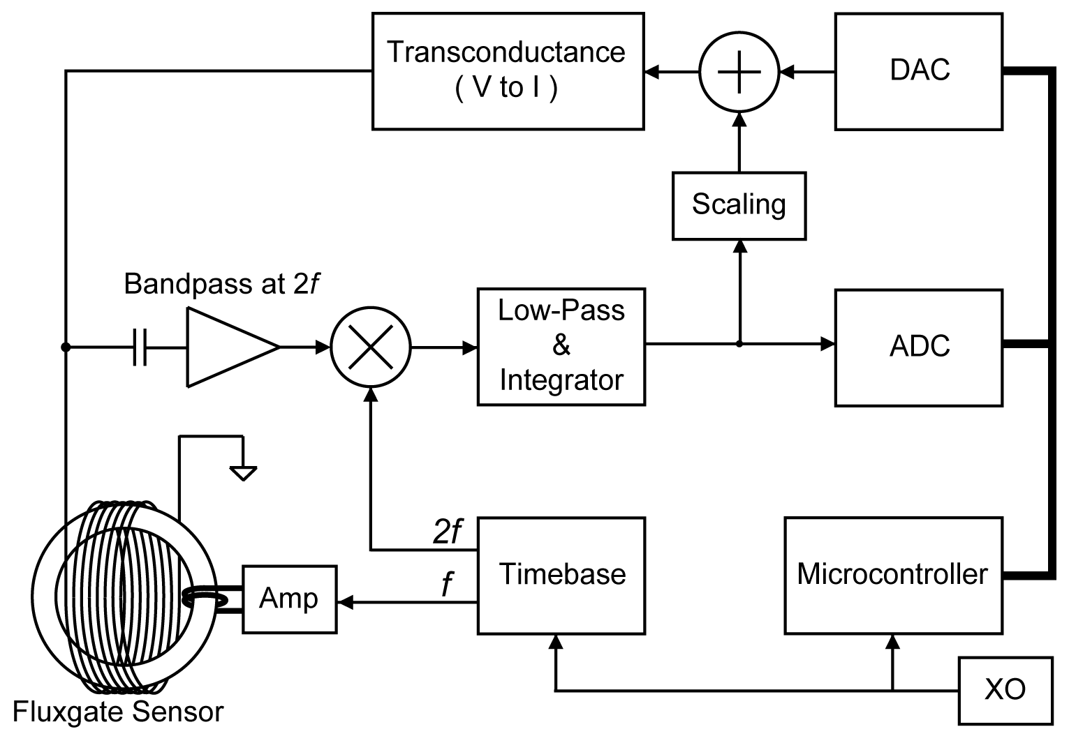
Figure 2Block diagram of the MGF instrument showing the offsetting design whereby a digital-to-analog (DAC) converter applies a digitally controlled offset current to the sensor to partially cancel the ambient magnetic field. Reproduced from Wallis et al. (2015).
This offsetting design allows the instrument to preserve its resolution even in the near-Earth magnetic field at ∼325 km altitude (orbit perigee) rather than having to enter a lower resolution mode, as is the case in gain-ranging instruments such as the Electric and Magnetic Field Instrument Suite and Integrated Science (EMFISIS) on the Radiation Belt Storm Probes (RBSP) mission (Kletzing et al., 2013). However, this offsetting design poses challenges in space applications as the instrument must continuously slew the magnetic offset in each of the three axes to correctly track the continuously changing field in the frame of the sensor as the spacecraft orbits the Earth. Updates to the DAC take a finite amount of time to propagate through the transconductance circuit, and the amount of magnetic feedback experienced by the sensor varies while the DAC and filter are settling, creating non-physical transients in the reconstructed measurement of the magnetic field.
This transient behavior is typically characterized and removed following each DAC update to reconstruct an accurate measurement of the local magnetic field. However, a bug in the as-launched MGF firmware caused variable timing between the updates to the DAC and the ADC sampling of the residual field in each magnetometer channel. Consequently, the ADC sampled an arbitrary phase of the settling filter response, and the transient in the reconstructed magnetic measurement varied and could not be characterized and subtracted.
This behavior was verified in the laboratory by placing the engineering spare sensor in a magnetic shield and applying a slowly varying magnetic ramp (Fig. 3a). The transients after each DAC update create the ticks visible on the ramped magnetic field. Figure 3b shows sequences of measurements adjusted to zero before a DAC update, showing the envelope of possible transients caused by sampling the settling filter after a non-constant delay. New instrument firmware (V1.3.0) was developed to make the offset between the DAC update to ADC sampling constant; this stabilized the dynamic behavior of the DAC updates (Fig. 3c). The transients did not appear to depend on the slew rate of the field used to exercise the engineering sensor and scale with the size of the feedback step. This suggests the characterized transients should be repeatable even in the more erratic environmental fields experienced on orbit, although this is difficult to verify experimentally.
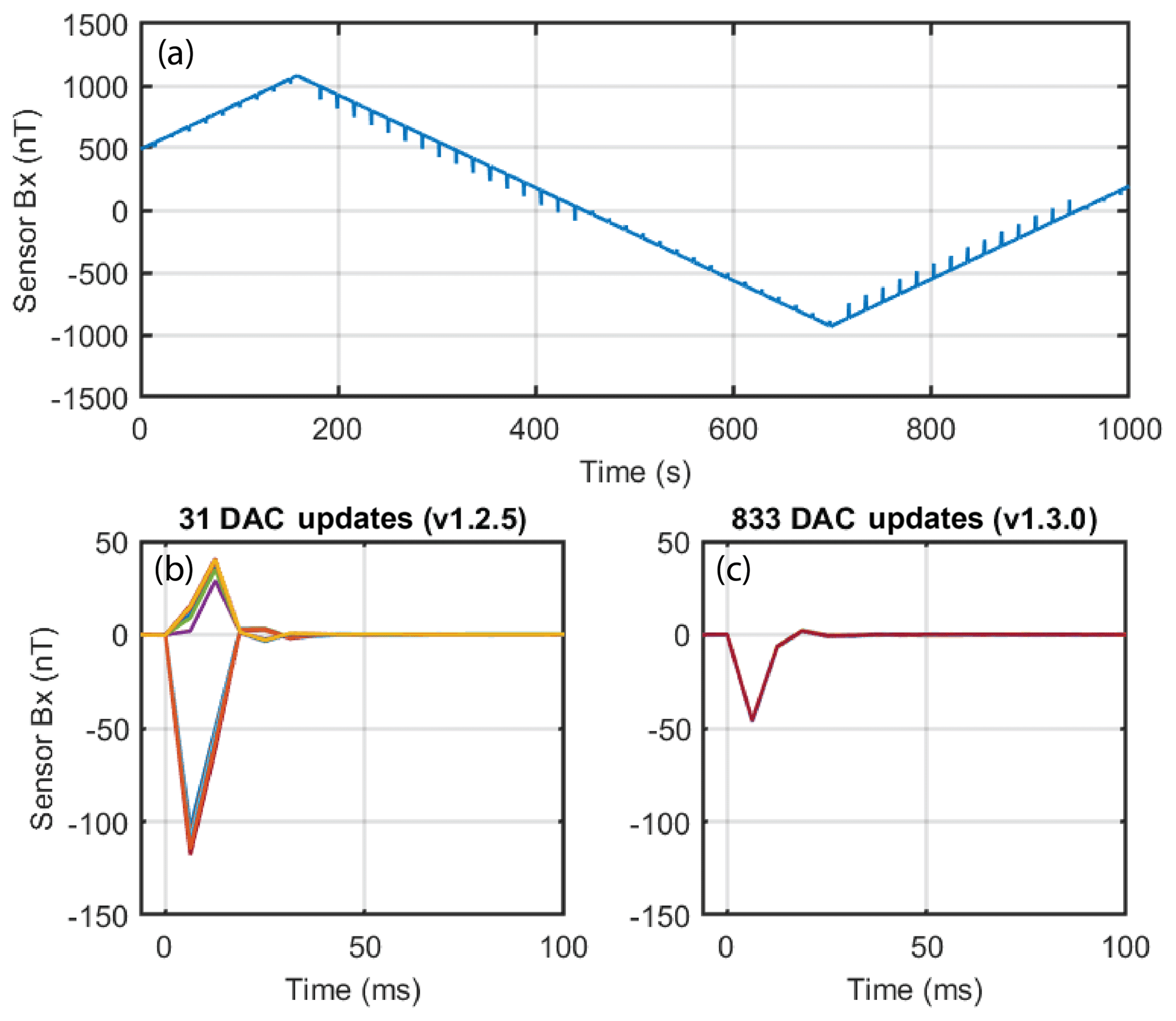
Figure 3(a) Ramped test magnetic field applied in the laboratory to demonstrate the transient behavior of the engineering spare magnetometer. The ticks in the measured field are uncompensated feedback transients. (b) Zoomed and de-trended view of overplotted transients observed in the output of the sensor due to the original variability timing of the digital magnetic feedback. (c) Same but with the firmware updated to provide repeatable timing.
The two MGF flight instruments received the new firmware in April 2014. However, processing the data generated by the new firmware was complicated by the transient behavior after a DAC update being unique to each individual sensor and electronics hardware combination. The transient behavior of the engineering spare hardware, which was simple to characterize in the laboratory, could not be directly applied to the updated flight hardware on orbit.
The challenge was to characterize the transient behavior on each axis of the inboard and outboard flight sensors sufficiently to allow for compensation of the transients in the post-processed flight data. This was further complicated by the on-orbit data being contaminated by 5 to 25 nT of local magnetic noise from the reaction wheels.
The laboratory characterization technique cannot be directly applied to in situ data. The reaction wheels used to orient the spacecraft create a complex ∼10–15 Hz local field (as-launched, wheels rates were changed in 2016 as described below) that varies on the same timescale as the transients; filtering to remove the sinusoidal signal created by the reaction wheels affects the impulse response of the system and modifies the transient behavior, resulting in an incorrect correction.
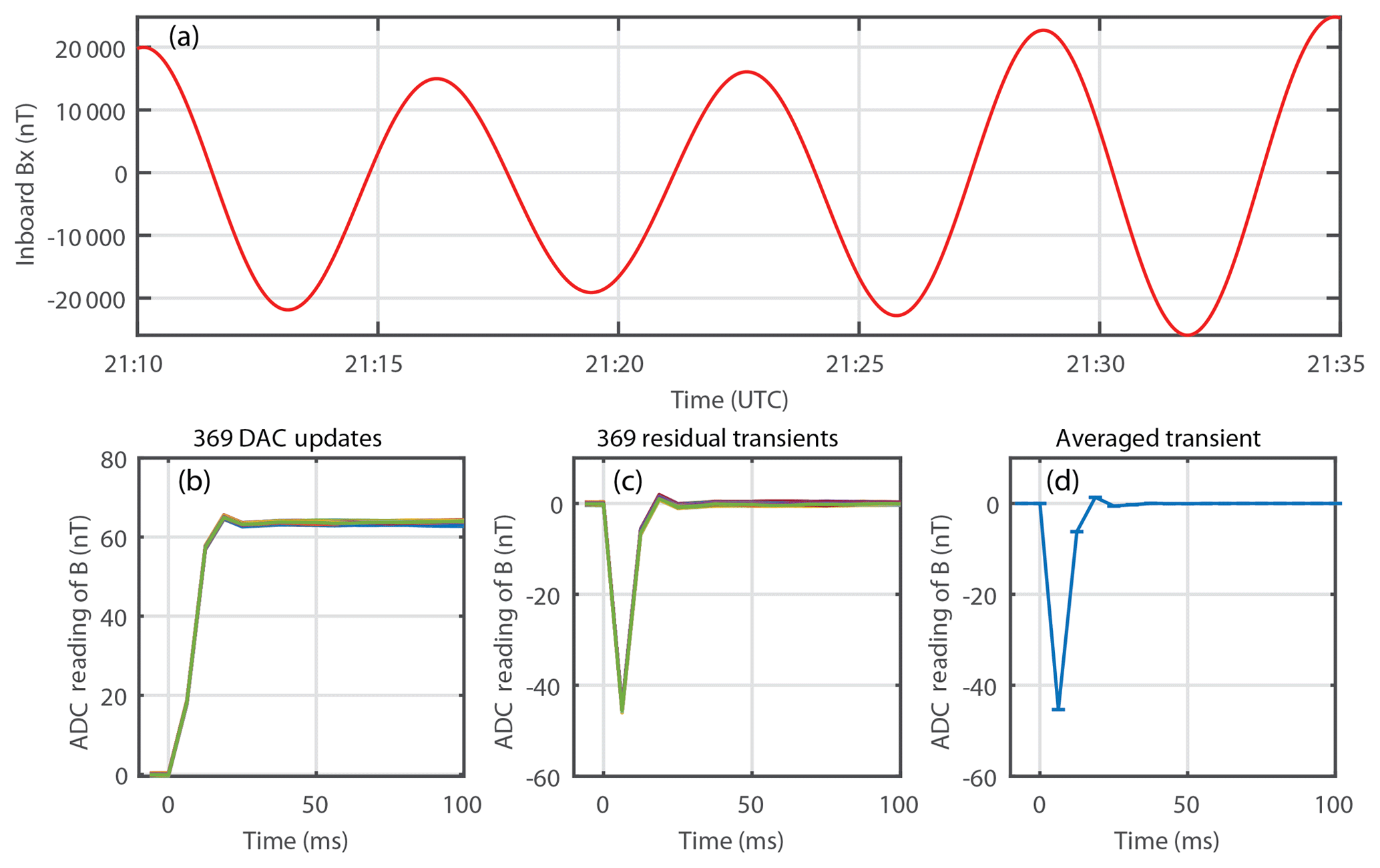
Figure 4(a) Time series of sensor x axis showing the spacecraft spin with no reaction wheels powered on. (b) Overplot of 369 ADC sequences following DAC updates. (c) Same but with the expected step from the DAC update removed to show the residual transient. (d) Median average estimate of the transient used to correct the measured data. Error bars show the variance of the averaged ADC sequences.
For mission reliability reasons, the wheels are not permitted to be commanded off during normal operations as there is a stiction failure mode that had been observed in prior missions. Serendipitously, the onboard spacecraft computer has experienced a little over a dozen reboots since launch, many of these occurring over the South Atlantic Anomaly. As part of the recovery, the spacecraft enters a safehold mode where it automatically shuts down the reaction wheels. In this mode, the magnetorquers orient the main solar panel to the sun and trigger a ∼400 s spin around the instrument z axis to minimize differential heating due to sunlight (Fig. 4, top). Normally, no science data are acquired in this mode. However, the spacecraft operations team developed a special recovery process in which the MGF was operated for ∼30 min observing sessions before the spacecraft was fully restored into normal operations, which included powering back on the reaction wheels.
Two of these 30 min no-wheel intervals were used for an initial fit of the transient behavior. The calibration was undertaken by looking for DAC updates on each channel that were separated by at least 32 samples to ensure that the analog electronics had fully settled before they were perturbed by the subsequent DAC update. Further, the transients weakly couple between the x, y, and z axes of each sensor so intervals were only used if the other two channels had no updates during the period to prevent the characterization of each channel being contaminated by updates on the other two channels. The primary spacecraft motion was rotation around the z axis (Fig. 4a), which provided ∼2000 usable DAC updates in x and y but only ∼10 in z.
The sinusoidal trend created by the spacecraft spin can be approximated as linear over the 32 sample (200 ms) interval allowing the samples following a DAC update to be estimated and the transient tick to be measured. Robust linear regression was used to fit and remove any background trend during the interval (Fig. 4b). The known scaling between the feedback from the DAC (32 nT per bit) and the ADC forward loop (0.0625 nT per bit) was used to subtract the step function expected after a DAC update and reveal the transient behavior of that axis (Fig. 4c). Robust linear regression was used again to ensure that the transient starts and ends at 0 nT, and a median average was used to estimate the transient correction while ignoring outlying values (Fig. 4d).
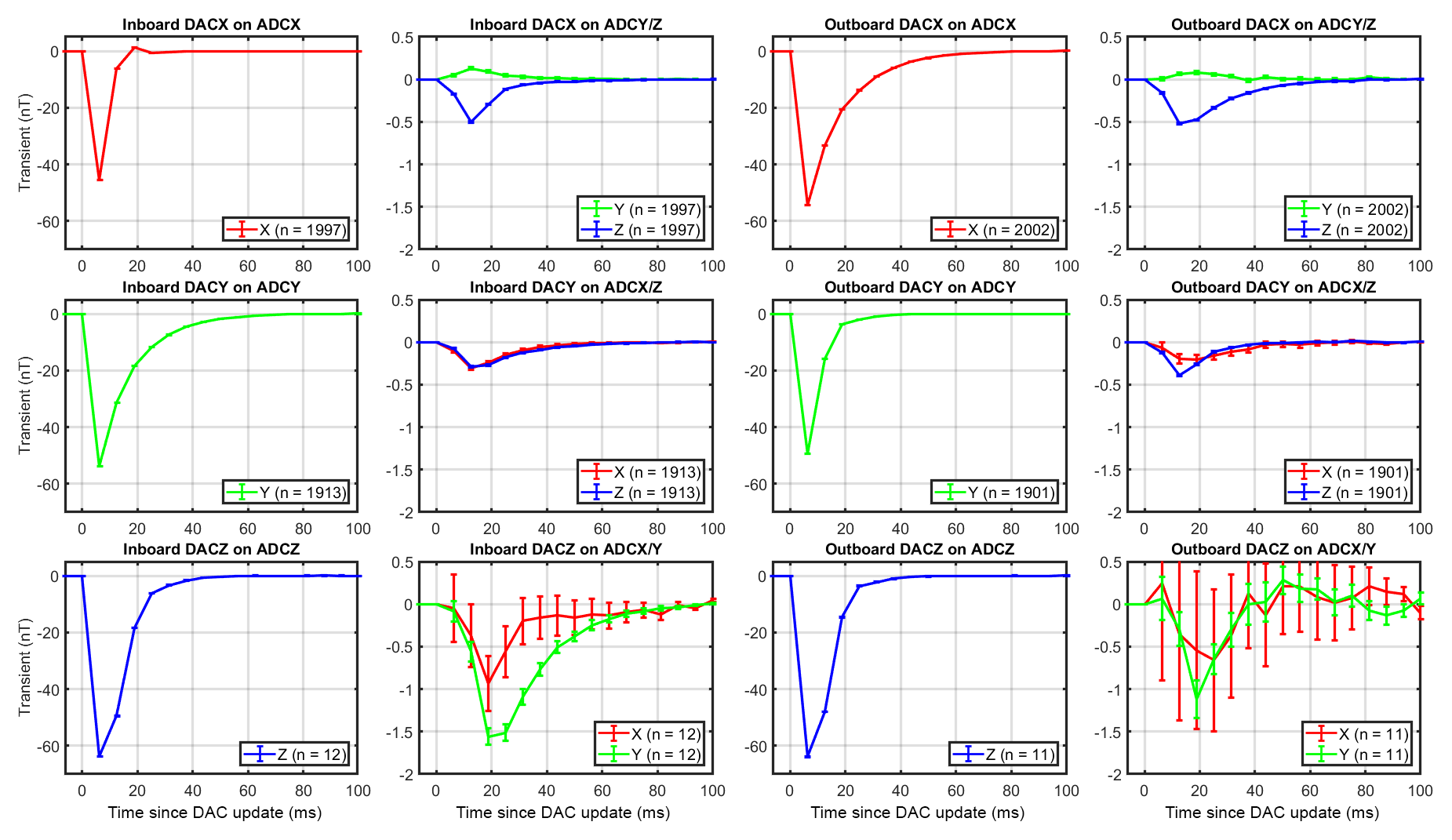
Figure 5Estimates of transient behavior of each channel of both MGF instruments. The larger transients due to DAC z may be related to z being a series connection of two sense coils. The uncertainty in the z channel estimates results from fewer usable DAC updates as the spacecraft is primarily rotating around the instrument z axis. The cross-channel transients are displayed on an expanded scale.
Figure 5 shows the 18 corrections fitted from the spinning no-wheel data corresponding to the instrumental x, y, and z axes on both the inboard and outboard MGF sensors. The ADC transient resulting from a DAC update on the same channel in the instrument (e.g., DAC x on ADC x were ∼40–60 nT, whereas the cross-channel transients (e.g., DAC x on ADC y) were ∼0.5–2.0 nT. Cross-channel updates due to DAC z were larger than those resulting from DAC x or y; this may be related to channel z being constructed from the series connection of the sense windings around both ring cores in the sensor (Wallis et al., 2015).
Applying these fitted correction coefficients to several years of MGF observations showed that the transient behavior was dependent on temperature of the instruments' electronics package (the sensor temperatures were recorded as well but did not have a significant effect). However, due to technical restrictions in the spacecraft recovery process, the safe-mode no-wheel data were only obtained after the MGF had been in the shadow of the spacecraft for some time, which caused the instruments to be unusually cold (−20 to −40 ∘C). Therefore, the fitted corrections are unsuitable for normal science operations that typically occur over a much wider range of warmer temperatures (up to +20 ∘C).
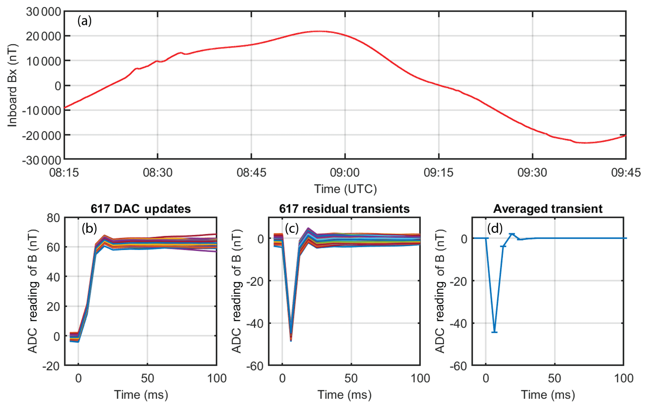
Figure 6Equivalent analysis to Fig. 4 but for an interval with slowed reaction wheels. (a) Time series of sensor x axis showing essentially one orbit of data. (b) Overplot of 617 ADC sequences following DAC updates. (c) Same but with the expected step from the DAC update removed to show the residual transient. (d) Median average estimate of the transient used to correct the measured data. Error bars show the variance of the averaged ADC sequences.
In 2016, one of Cassiope's original four reaction wheels failed. Rebalancing the spacecraft attitude control required that the remaining three wheels be slowed from ∼15 to ∼1 Hz to stabilize the spacecraft attitude control system. This impacted the MGF magnetic data quality but makes the reaction wheels' spin speed slow enough that their magnetic signatures can be fitted and removed on the timescale of the transients. Figure 6c shows an overplot of 617 ADC sequences from the inboard Bx channel following updates to the magnetic feedback DAC on the same channel. The background trend of the local magnetic field has been removed by subtracting a robust linear regression that excludes the region affected by the transient. Although the scatter is visibly broader than for the no-wheel data shown in Fig. 4, the trend of the transient is clear and can be extracted by median filtering as shown in Fig. 6d.
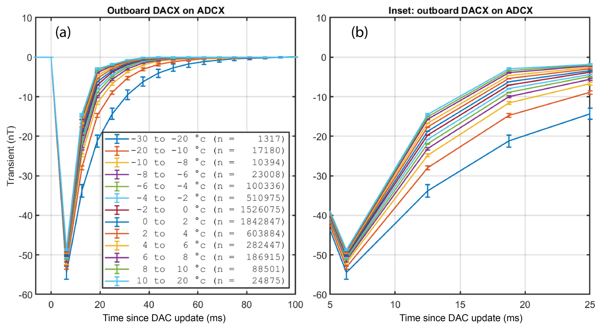
Figure 7(a) The coefficients used to correct the transient following a DAC update in each instrument channel were found to be temperature dependent. The “n” indicates the number of transients averaged in that temperature band. (b) Expanded timescale to show ordering of the temperature-dependent ticks.
Transient fitting was repeated for all data taken after the wheels were slowed (June 2016 to December 2018). The data were then sorted into temperature bands from −30 to +20 ∘C and fitted as before to create temperature-dependent correction coefficients, shown in Fig. 7.
Corrections for the transients in the MGF data are applied by subtracting the characterized ADC transients from the reported ADC readings after each DAC update. Figure 8 shows a representative correction for DAC ±2 steps showing the uncompensated (dashed) and compensated (solid) reconstructed magnetic field in the x, y, and z channels. The compensation suppresses the transient behavior by a factor of at least 100 in each case.
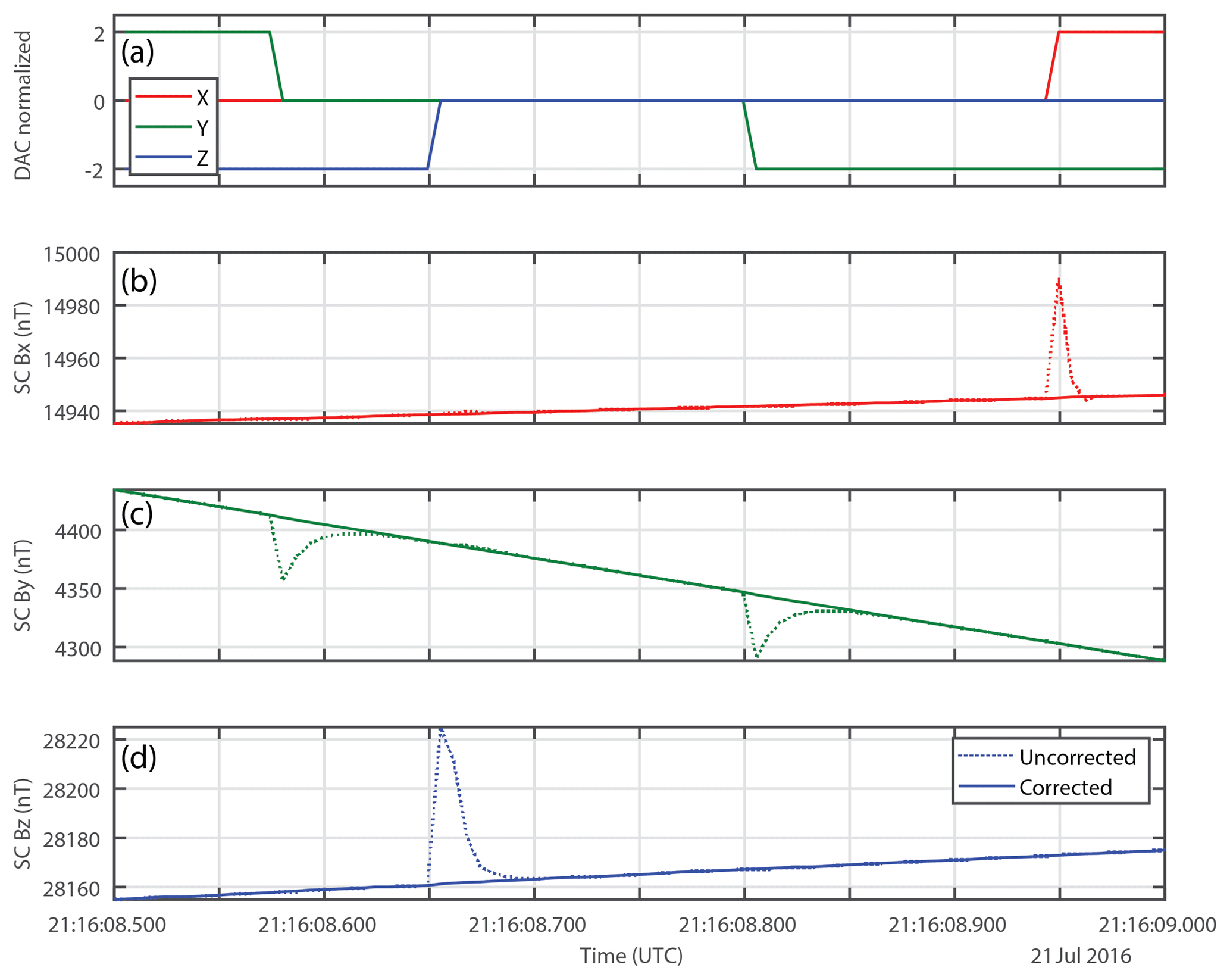
Figure 8Uncorrected and corrected time series following DAC updates (a) for the x (b), y (c), and z (d) instrument axes.
Figure 1 uses a dynamic spectrum to visualize the spectral content of the uncompensated (a) and compensated (b) time series. Note that the amplitude of the vertical striping, caused by the broadband content of the transients, is almost completely suppressed.
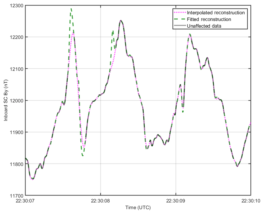
Figure 9Cross-track magnetic field measurements of an ion heating event studied by Shen et al. (2018) with high-amplitude small-scale magnetic perturbations. The presented transient compensation technique captures ∼100 nT and ∼200 ms features which are lost completely when the data are reconstructed by dropping data affected by DAC updates and interpolating.
Figure 9 shows an event studied in Shen et al. (2018) where e-POP encountered large in situ field variations associated with ion heating and downflow that require instrumental slew rates exceeding 3000 nT s−1. These large-amplitude, short-duration magnetic field variations cause near-continuous stepping of the digital magnetic feedback to track the field. Consequently, feedback transients affect most of the data (Fig. 9). The first attempt to mitigate the instrument transients (MGF data processing software version 1.0.0 and above) invalidated all affected samples and then interpolated (Fig. 9, dashed pink). The reconstruction described here (MGF data processing software version 2.0.0, Fig. 9, solid green) overlaps the previous reconstruction when the underlying data are not affected by DAC update transients (Fig. 9, black). However, it is evident that the interpolated version can miss entire structures of ∼100 nT and 100 ms duration in regions of high instrument slew rates.
The described in situ characterization and compensation successfully mitigates the transients in the MGF data following updates to the digital magnetic feedback. The current compensation is based on 2.5 years of data and the transients have been fit to better than 0.5 nT for most instrument temperatures. This correction allows MGF to resolve large-amplitude and small-scale magnetic features of ∼100 nT and <1 km, which were missed entirely by previous data interpolation methods. Ongoing data collection is expected to allow us to continue to refine these correction coefficients providing cleaner and more useful spectral plots. More generally, this characterization process should apply to other situations where the dynamics of an offsetting instrument must be calibrated in situ.
The MGF data processing software (mgftools) described herein is maintained in the Cassiope mission Subversion repository. Release versions of this code are available at: https://epop.phys.ucalgary.ca/data/ (Miles et al., 2019).
Science data from the e-POP mission are available via http via an open date-driven folder tree at: https://epop-data.phys.ucalgary.ca/ (last access: 12 August 2019). e-POP data can also be accessed using the e-POP Data Explorer (eDEx) tool available at: https://epop.phys.ucalgary.ca/data/#edex (White, 2018).
DMM is the PI for the MGF payload on e-POP, developed the data product processing code for the MGF, performed the in situ calibration described here, and prepared the paper with contributions from all co-authors. ADH developed the ground data-product processing software infrastructure and helped test the V2.0.0 data processing code. GAE is the e-POP mission manager and coordinated the special safe-mode operations that produced the wheel-free data used in this paper.
The authors declare that they have no conflict of interest.
The authors wish to thank Don D. Wallis, B. Barry Narod, John R. Bennest, and Jonathan E. Schmidt for insight into the operation of the MGF instrument. Andrew W. Yau, Michael J. Miles, Sarah E. Miles, and Robert M. Broadfoot provided comments on an early copy of this paper.
This research has been supported by the European Space Agency (Third Party Mission Programme), the Canadian Space Agency (Cassiope/e-POP Operations), and the University of Iowa (College of Liberal Arts and Sciences New Faculty Startup).
This paper was edited by Valery Korepanov and reviewed by two anonymous referees.
Acuña, M. H., Scearce, C. S., Seek, J., and Scheifele, J.: The MAGSAT vector magnetometer: A precision fluxgate magnetometer for the measurement of the geomagnetic field, National Aeronautics and Space Administration, Goddard Space Flight Center, Greenbelt, Maryland, USA, 1978.
Kletzing, C. A., Kurth, W. S., Acuna, M., MacDowall, R. J., Torbert, R. B., Averkamp, T., Bodet, D., Bounds, S. R., Chutter, M., Connerney, J., Crawford, D., Dolan, J. S., Dvorsky, R., Hospodarsky, G. B., Howard, J., Jordanova, V., Johnson, R. A., Kirchner, D. L., Mokrzycki, B., Needell, G., Odom, J., Mark, D., Pfaff, R., Phillips, J. R., Piker, C. W., Remington, S. L., Rowland, D., Santolik, O., Schnurr, R., Sheppard, D., Smith, C. W., Thorne, R. M., and Tyler, J.: The Electric and Magnetic Field Instrument Suite and Integrated Science (EMFISIS) on RBSP, Space Sci. Rev., 179, 127–181, https://doi.org/10.1007/s11214-013-9993-6, 2013.
Miles, D. M., Bennest, J. R., Mann, I. R., and Millling, D. K.: A radiation hardened digital fluxgate magnetometer for space applications, Geosci. Instrum. Method. Data Syst., 2, 213–224, https://doi.org/10.5194/gi-2-213-2013, 2013.
Miles, D. M., Mann, I. R., Kale, A., Milling, D. K., Narod, B. B., Bennest, J. R., Barona, D., and Unsworth, M. J.: The effect of winding and core support material on the thermal gain dependence of a fluxgate magnetometer sensor, Geosci. Instrum. Method. Data Syst., 6, 377–396, https://doi.org/10.5194/gi-6-377-2017, 2017.
Miles, D. M., Broadfoot, R. M., and Piker, C. W.: mgftools matlab source, Alpha 1, available at: https://epop.phys.ucalgary.ca/data/, last access: 17 July 2019.
Narod, B. B. and Bennest, J. R.: Ring-core fluxgate magnetometers for use as observatory variometers, Phys. Earth Planet. In., 59, 23–28, 1990.
Primdahl, F.: Temperature compensation of fluxgate magnetometers, IEEE T. Magn., 6, 819–822, 1970.
Primdahl, F.: The fluxgate magnetometer, J. Phys. E, 12, 241–253, 1979.
Shen, Y., Knudsen, D. J., Burchill, J. K., Howarth, A. D., Yau, A. W., Miles, D. M., James, H. G., Perry, G. W., and Cogger, L.: Low-Altitude Ion Heating, Downflowing Ions, and BBELF Waves in the Return Current Region, J. Geophys. Res.-Space, 123, 3087–3110, https://doi.org/10.1002/2017JA024955, 2018.
Wallis, D. D., Miles, D. M., Narod, B. B., Bennest, J. R., Murphy, K. R., Mann, I. R., and Yau, A. W.: The CASSIOPE/e-POP Magnetic Field Instrument (MGF), Space Sci. Rev., 189, 27–39, https://doi.org/10.1007/s11214-014-0105-z, 2015.
White, A. S.: e-POP Data Explorer (eDEx), V1.2.5, available at https://epop.phys.ucalgary.ca/data/#edex, last access: 23 October 2018.
Yau, A. W. and James, H. G.: CASSIOPE Enhanced Polar Outflow Probe (e-POP) Mission Overview, Space Sci. Rev., 189, 3–14, https://doi.org/10.1007/s11214-015-0135-1, 2015.