the Creative Commons Attribution 4.0 License.
the Creative Commons Attribution 4.0 License.
 | 26 Feb 2026
The development of a reference corner cube inertial suspension device
Bing Zhang
Xiaoyi Zhu
Bing Xue
Lili Xing
Yanxiong Wu
Peng Su
Xiaolei Wang
Yuru Wang
Shuaibo Zhao
Chuhan Wang
Kaihang Liu
The seismometer synchronous observation and zero crossing methods are applied to laser interferometer absolute gravimeter to suppress the vibration interference. However, during the synchronous observation of the seismometer and the gravimeter, the observation point of the seismometer does not coincide with the reference corner cube in space, resulting in spatial dislocation and impossibility to accurately reflect the vibration state of the reference corner cube. So it can be considered to accurately measure the vibration acceleration of the reference corner cube by inertial suspension. In this paper, an open-loop reference corner cube inertial suspension device (RCCISD) hanging the reference corner cube was developed based on the principle of seismometer, which is used to measure the vibration acceleration of the reference corner cube of the laser interferometer absolute gravimeter. Experimental test results show that the power spectrum of gravitational acceleration calculated by an interference fringe observed jointly by the RCCISD is about 40 dB lower than that of the reference corner cube directly placed on the ground. The RCCISD can restrain the vibration interference to a certain extent. At the same time, it can not only measure the vibration of the reference corner cube more accurately than the seismograph synchronous observation method, but also the volume is about smaller than the Super-Spring, so it can greatly reduce the height of the gravimeter.
- Article
(981 KB) - Full-text XML
- BibTeX
- EndNote


During the falling process of the free-falling corner cube in absolute gravimeter, the change of the displacement between the free-falling corner cube and the reference corner cube forms a fringe signal. The falling trajectory of the free-falling corner cube relative to the reference corner cube can be reconstructed by extracting the zero-crossing information of the fringe signal. The gravity acceleration of the measuring point can then be obtained using the least-squares fitting of the trajectory (Niebauer et al., 1995; Wu, 2012; Hu et al., 2012). It is necessary to keep the reference corner cube stationary or its motion linear during the falling process to ensure the accuracy of the obtained gravitational acceleration. However, due to the environmental vibration and the free vibration of the free-falling corner cube control system, the reference corner cube presents a complex vibration mode during the free fall of the free-falling corner cube, causing errors to the measurement results (Wu et al., 2012; Long et al., 2012).
In 1993, USGS published a report on observation and Model of earthquake background noise (Peterson, 1993). The report gives the results of power spectrum analysis of normal earth background noise from many seismic stations around the world, and gives a new model of high earth noise (NHNM) and a new model of low earth noise (NLNM). The peak noise of the acceleration power spectrum in the 0.04–1 Hz band of the model comes from the interference of ocean waves, while the high-frequency noise above 1 Hz mainly comes from human activities, wind and other factors. Because the ocean area accounts for about 70 % of the earth's surface, the wave interference frequency is low and the propagation attenuation is slow, wave interference has become an unavoidable interference factor in absolute gravity measurement. In economically developed areas, human activity interference may also reach a very high range, which has become the primary factor affecting the accuracy of gravity measurement.
Most of the free fall stroke in the absolute gravimeter is about 20 cm, and the free fall time is about 0.2 s. It takes several seconds to carry out a measurement, and the repeated measurement period is generally about 10 s (Niebauer et al., 2011; Wu et al., 2017). For example, the FG5 absolute gravimeter can make 200 measurements in 30 min with an average interval of 9 s (Niebauer et al., 1995). If the repeated measurement period is 10 s, that is, the sampling rate is 0.1 Hz, according to the sampling theorem, any signal and interference whose frequency is higher than 0.05 Hz will be superimposed into the measured data in the form of frequency aliasing and become the largest source of random interference. The measurement accuracy is 2 µgal Hz, corresponding to the longitudinal coordinate −154 dB, it can be seen that the amplitude of wave interference may be 1000 times higher than the required measurement accuracy. Therefore, it is an important task in absolute gravity measurement to suppress the interference noise such as wave interference, man-made vibration interference and wind disturbance whose frequency is higher than that of 0.05 Hz.
At present, the FG5 series absolute gravimeter of Micro-G LaCoste Company of the United States is the only commercial high-precision absolute gravimeter with a measurement accuracy of 2 µgal ( m s−2) and an accuracy of 2 µgal Hz (quiet site) (Micro-g LaCoste, 2015). The FG5 absolute gravimeter adopts SuperSpring vibration isolation system and has a two-stage spring structure. The basic principle is that the position change of the reference corner cube relative to the auxiliary spring vibration isolation frame is detected by laser, and the upper end of the main spring is adjusted by active feedback compensation to make the secondary spring vibration isolation frame follow the motion of the reference corner cube. After feedback compensation, it is equivalent to an ultra-long period spring damping suspension system with a period of 30 s, so as to attenuate low frequency vibration interference and restrain the influence of ground pculsation on absolute gravity measurement (Yao and Wu, 2019).
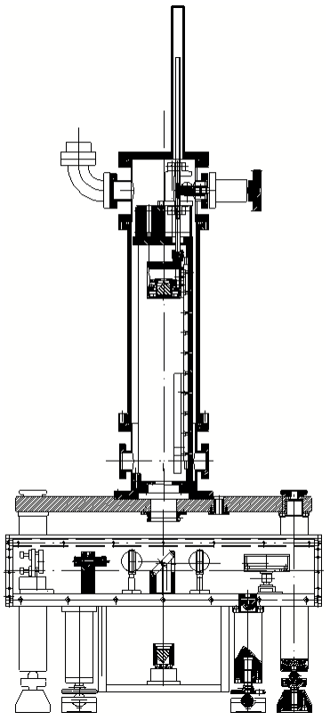
The free-falling corner cube driving mechanism of the Age-110 absolute gravimeter developed by the Institute of Geophysics, China Earthquake Administration, is mainly composed of gears, rack, carriage, guide rail, guide pillar, vacuum sealing parts, auxiliary support parts, servo motor, and the control system as shown in Fig. 1. The carriage is the free-fall carrier. The servo motor controls the carriage's lifting and release through the bite of the gear and the rack. The guide rail and rail strut are utilized to keep the carriage moving up and down along the vertical direction. The lifting height of the carriage is about 18 cm. The free-falling time of the free fall is about 0.2 s. The motion process of the carriage mainly includes uniform lifting, pausing for 10 s, accelerating fall, uniform falling, decelerating falling, and resting (Wu, 2011; Wu et al., 2012; Li, 2016).
With the acceleration of the falling, the bite between the motor gear and the rack produces the moment of inertia under the tension action, leading to high-speed motion friction, while the carriage and the guide rail also produce high-speed motion friction. In deceleration of the falling, the motor produces a reverse moment of inertia and motion friction. When the carriage displacement is equivalent to that of the free-falling corner cube, the two begin to contact to form an elastic collision, resulting in a specific inertia impulse. The gravimeter transmits the vibration caused by high-speed friction and elastic collision to the ground, causing the vibration of the reference corner cube by the ground coupling. The vibration interference runs through the whole process of free flight of the free-falling corner cube, superimposing on the whole laser interference fringes to affect the accuracy of gravity measurement. Therefore, the seismometer synchronous observation and zero crossing methods are applied to Age-110 to suppress the vibration interference. Age-110 uses the seismometer to place the seismometer at the 5 cm next to the reference corner cube for synchronous vibration observation and zero-crossing dotting algorithm for vibration compensation to achieve the purpose of vibration suppression as shown in Fig. 2.
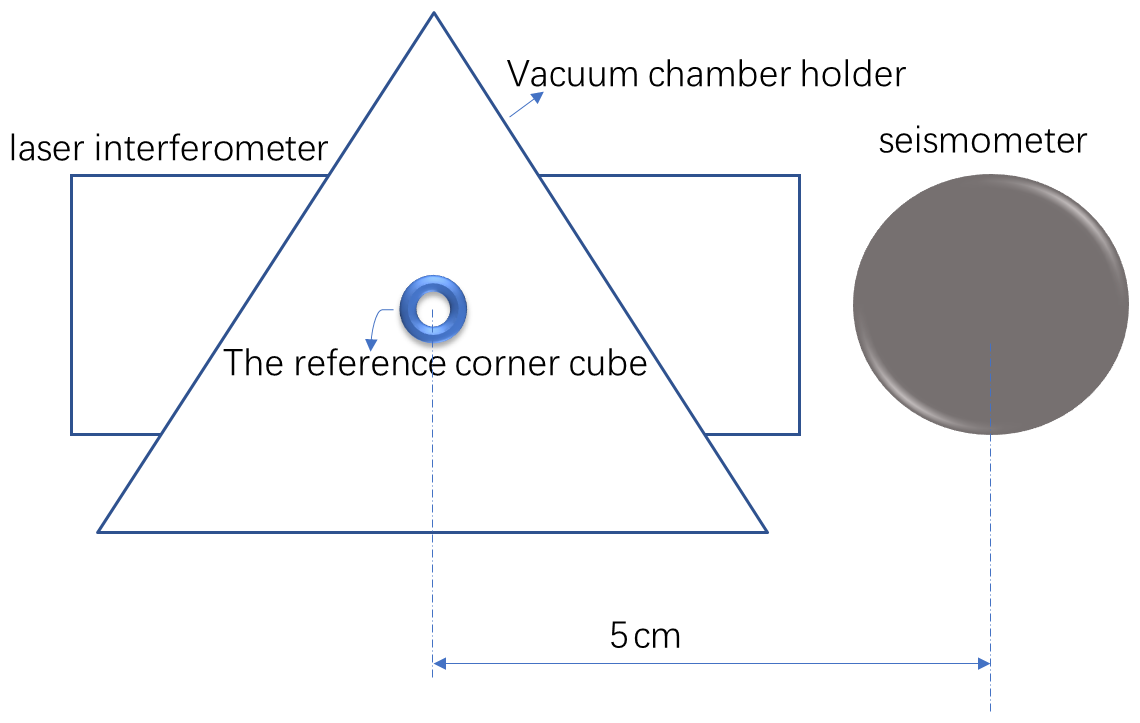
However, during the synchronous observation of the seismometer and the gravimeter, the observation point of the seismometer does not coincide with the reference corner cube in space, resulting in spatial dislocation, which cannot accurately reflect the vibration state of the reference corner cube. So, it is necessary to hang the reference corner cube on the elastic element to directly measure its vibration acceleration measurement for real-time compensation.
In this paper, an open-loop reference corner cube inertial suspension device (RCCISD) hanging the reference corner cube was developed based on the principle of seismometer, which is used to measure the vibration acceleration of the reference corner cube of the laser interferometer absolute gravimeter. Afterwards, the reference corner cube inertial suspension device was deployed to the Age-110 to test the function and the performance. RCCISD can not only measure reference corner cube vibration more accurately than seismograph synchronous observation method for vibration compensation of gravity measurement, but also is smaller than super-long spring and can greatly reduce the height of gravimeter.
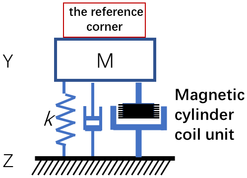
In order to directly measure and analyze the vibration data of the reference corner cube, the reference corner cube can be elastically suspended on the pendulum of the open-loop seismometer to design a new open-loop reference corner cube inertial suspension device. The motion of the pendulum is measured by an electromagnetic transducer. A coil is installed on the inertia magnetic bar to form the magnetic coil unit. The magnetic coil unit then is embedded into the gap of the magnetic cylinder to form the magnetic cylinder coil unit.The induced electromotive force is generated by the movement of the coil in the magnetic field, and the output of the voltage signal is used to reflect the acceleration of the frame to the ground motion. The principal model is shown as Fig. 3.
According to Faraday's law, the induced electromotive force produced by the coil in the loop is ev = ddt, which dΦ is the variation of magnetic flux. When the coil has N turns, the radius of the coil is r and the magnetic induction intensity is B. when the center of the coil moves away from dx:
Therefore, the induced electromotive force can be written as
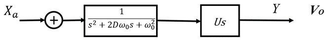
Where U is the voltage sensitivity. The larger the U, the higher the sensitivity of the device. As shown in Fig. 4, the transfer function of the output voltage to the ground vibration acceleration is
The reference corner cube inertial suspension device (RCCISD) adopts the mechatronics design of the force balance principle, including the reference corner cube M, elastic suspension elements, transducers, amplifiers, working coils and output circuits (Li et al., 2018).
The inertia force caused by the ground motion makes the reference corner cube M deviate from the equilibrium position. Then, the deviate drives the coil cutting magnetic field to output the voltage signal and produce an electromagnetic force acting on the M. The direction of the electromagnetic force is opposite to the inertia force felt by the M, whose magnitude is basically the same to the electromagnetic force, so that the motion amplitude of the M is as small as possible. Because the inertia force felt by the M is proportional to the speed of the ground motion and the electromagnetic force acting on the M is proportional to the current passing through the electromagnetic coil, an electromechanical coupling system is formed. So, the electrical signal output proportional to the ground motion is obtained.
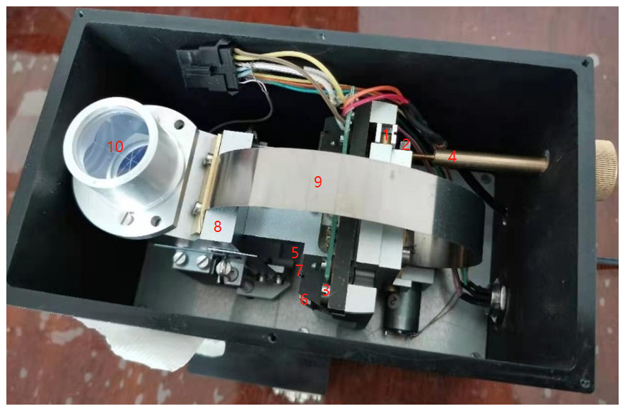
The composition and structure of the RCCISD is shown in Fig. 5. The mechanical display of the suspension reference corner cube is shown in Fig. 5, for example, where the elastic vibration system is composed of pendulum body (8 in Fig. 5), Reed (9 in Fig. 5), reference corner cube (10 in Fig. 5), etc.; the energy exchange system consists of a calibration coil (5 in Fig. 5), a magnetic cylinder (6 in Fig. 5), a working main coil (7 in Fig. 5), and other components (Teng, 2001).

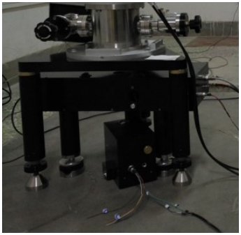
The elastic system adopts rotary compound pendulum structure, with cross-spring as rotation shaft. The leaf spring is used to be the main suspension, which is equipped with mechanical period adjusting screw and zero adjusting screw. The heavy hammer locking and the cross-spring locking are combined to the locking device. The physical figure is shown in Fig. 6, and the physical size is 20 cm ∗ 16 cm ∗ 20 cm, which is about of the super-long spring volume of the FG5 gravimeter.
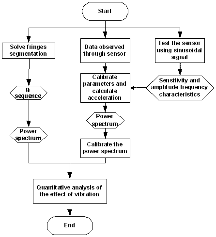
4.1 Data processing algorithm
The vibration of the reference corner cube is homologous to the vibration information contained in the laser interference fringes. Since the vibration interference is coupled to the reference corner cube through the ground, the influence of the vibration can be evaluated through synchronous measurement of the ground vibration (Lv et al., 2020).
4.2 Shaking table experiment
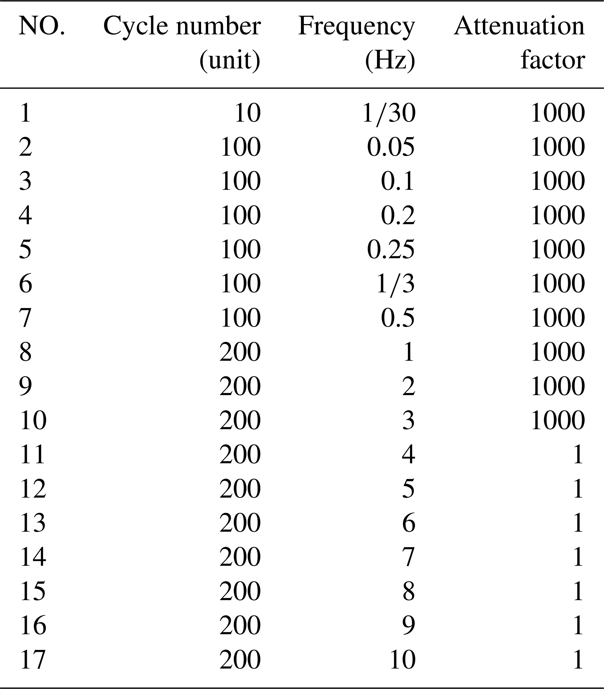
The RCCISD is tested on the shaking table (Ma et al., 2014), and the test data are shown in Table 1.
The transfer function of the RCCISD is:
ω0 is the natural angular frequency of oscillation. D is damping. A0 is sensitivity.
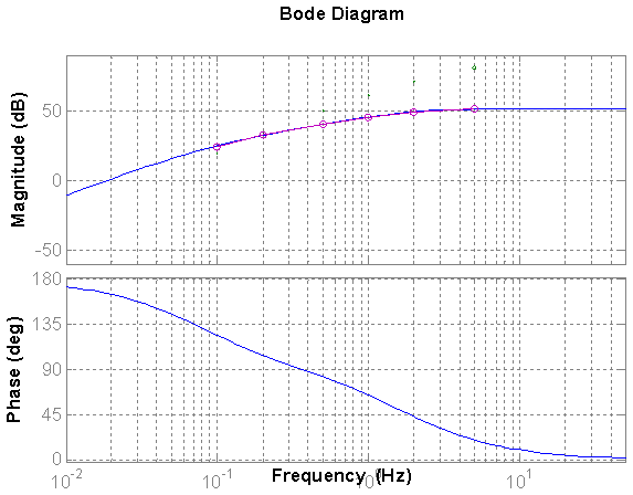
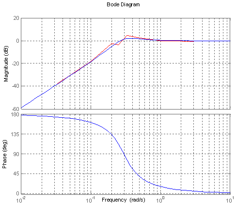
Using the data in Table 1 for the transfer function fitting, the natural oscillation angular frequency is ω0=2.2942 rad s−1, that is, natural oscillation frequency is f0=0.3651 Hz. The sensitivity is A0=387.7 V m−1 s−1. The fitted amplitude-frequency characteristic curve is shown in Fig. 8. In the picture, the red circle is the experimental data and the blue line is the fitting curve. The device shows high-pass characteristics.The transfer function of the RCCISD using the shake table test data is used to roughly determine the natural frequency and frequency response curve of RCCISD, and to provide a reference for setting parameters for sinusoidal calibration.
4.3 Transfer function calibration of the RCCISD
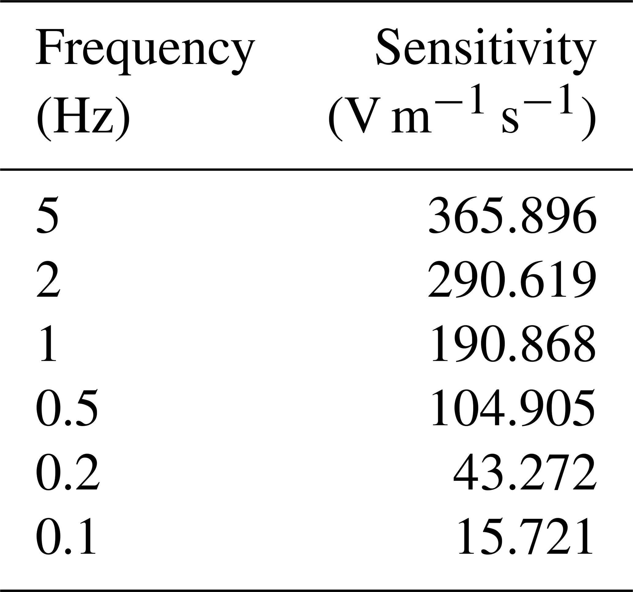
Before the observation experiment, the RCCISD was sinusoidal calibrated with 17 calibration frequencies (Lin and Cui, 2015; Zhang et al., 2016; Lv, et al., 2020), as shown in Table 2 The calibration data is shown in Fig. 9.
Using the calibrated data, 1 Hz was taken as the normalized frequency, and the normalized sensitivity of each frequency point was calculated in the frequency domain through FFT and ABS. The amplitude-frequency characteristics of the RCCISD could be obtained according to the calibrated data and sensitivity (Xue, 2021), as shown in Fig. 7. The red is calibration test data and the blue is the fitting curve. Through sinusoidal calibration, we can fit the more accurate transfer function of RCCISD in the experimental test, so as to facilitate the more accurate removal of the frequency response of RCCISD in the subsequent gravity acceleration measurement data processing.
Shaking table testing is primarily used to test the amplitude-frequency characteristics of instruments. It is an objective test of absolute quantities, and the Shaking table's ability to cover the frequency bandwidth is relatively weak, especially toward longer periods. The amplitude-frequency characteristics of instruments may change during prolonged use or in specific environments, so it is very necessary to perform a sinusoidal calibration test on the instrument before a particular use to calibrate the amplitude-frequency characteristics. Figure 9 in the article shows the amplitude-frequency characteristics normalized based on the results of the sinusoidal calibration test before using the RCCISD for experiments. This result is consistent with the vibration table test results in Fig. 8.
4.4 Joint experimental test of RCCISD and Age-110 laser interference absolute gravimeter
The joint observation experiment of Age-110 laser interference absolute gravimeter and RCCISD is carried out in the laboratory, as shown in Fig. 10. The gravimeter ran for one hour with the laser interference fringe data and vibration data from the RCCISD recorded (Wu et al., 2012).
4.5 Vibration acceleration data processing
The algorithm in Sect. 4.1 was applied to obtain the vibration acceleration measured by the RCCISD, as shown in Fig. 11. The periodic vibration signal of gravimeter during operation can be clearly seen. The vibration maximum occurs every 60 s, which is consistent with a falling period of 60 s for the free-falling corner cube. The coordinate in the picture is the data sampling sequence, and the sampling rate is 500 sps, that is, every 500 pieces of data in the sequence is 1 s. It is obvious that the periodic vibration signal of the gravimeter is running, and the peak-to-peak value of the vibration acceleration is about 0.2 m s−2.
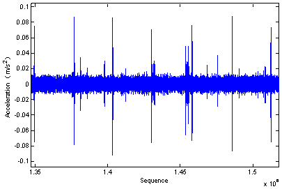
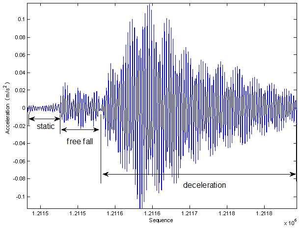
The vibration signal of the free-falling corner cube during its one free fall is shown in Fig. 12, which is part of one vibration period in Fig. 11. It can be seen that the process of a free-falling corner cube is static, free fall and deceleration (Wu, 2011). The free fall time of the free-falling corner cube is about 0.2 s. The vibration caused by deceleration impact is maintained for about 0.5 s .The amount of vibration caused by deceleration of the free-falling corner cube is about five times the amount of vibration during the free fall.
4.6 Gravity acceleration solution
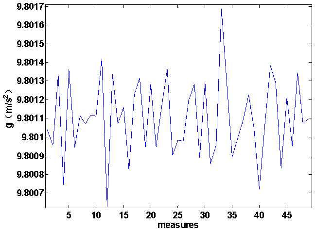
The interference fringes of Age-110 absolute gravimeter were collected. Each interference fringe lasts for about 0.6 s, whose effective part is about 0.15 s. The sequence of absolute gravitational acceleration values are calculated (Tsubokawa and Svitlov, 1999; Klopping et al., 1991; Qian et al., 2018; Svitlov et al., 2010), as shown in Fig. 13. The corresponding sampling frequency is 500 Hz.
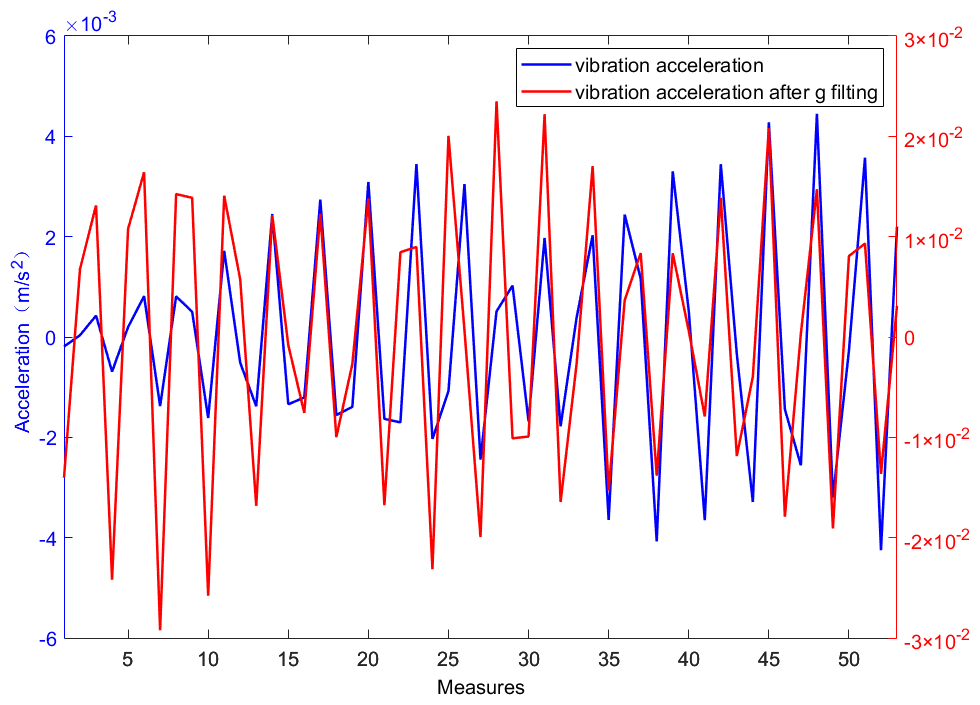
The gravity acceleration value sequence is solved by using an interference fringe to filter the vibration acceleration sequence in the free fall phase measured by the reference corner cube inertial suspension device, and the correlation is calculated, as shown in Fig. 14. it can be seen that the two waveforms are consistent in shape, but their amplitudes differ by an order of magnitude, and the vibration acceleration is one order of magnitude smaller than the g value sequence.
The instantaneous phase of the laser interference fringe signal is extracted based on the analytical signal processing algorithm, and the correlation analysis is carried out by combining the interference signal recorded by the single free fall of the falling body and the background vibration acceleration data directly placed on the ground by a wide band reference corner cube. It provides technical support for the establishment of the theoretical model of vibration interference suppression of absolute gravimeter. The method of vibration measurement and compensation requires high technical details and implementation technology. in the design and implementation, it is necessary to integrate the reference corner cube and vibration measurement system with other parts of the gravimeter. It is necessary to directly measure the vibration of the reference corner cube. Placing the reference corner cube on the pendulum of the elastic suspension of the seismograph can be directly measured and used for vibration compensation.
4.7 Quantitative analysis of vibration effect
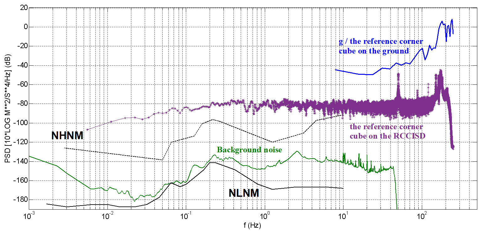
Because the vibration interference is coupled to the reference corner cube through the ground, the vibration of the reference corner cube is the same as the vibration information contained in the laser interference fringes, so the result of the full waveform of the laser interference fringes is the same as the vibration mode of the reference corner cube, which is equivalent to measuring the vibration of the reference corner cube. The vibration and noise power spectral density (PSD) of the free fall process observed by the reference corner cube directly placed on the ground and the RCCISD is calculated, as shown in Fig. 15 (Peterson, 1993; Xue, 2021). The blue is the PSD of gravity acceleration calculated by an interference fringe when the reference corner cube is placed directly on the ground. The pink is the PSD of gravity acceleration calculated by an interference fringe when the reference corner cube is placed on the RCCISD. The purple is the PSD of vibration noise recorded by the RCCISD during the gravimeter operation for one hour.
It can be seen from Fig. 15 that the vibration and noise of the absolute gravimeter is higher than that of the earth's high noise model NHNM. When the reference corner cube is placed directly on the ground and observed by the inertia suspension device of the reference corner cube, the shape of the vibration and noise power spectrum in the process of free fall is similar. In the frequency band above 7 Hz, the vibration power of the reference corner cube jointly observed by the reference corner cube inertial suspension (RCCISD) is about 40 dB lower than that of the reference corner cube directly placed on the ground. In other words, the RCCISD has a certain inhibition effect on high-frequency vibration interference, which is better than that of the reference corner cube directly placed on the ground. However, there is parasitic resonance around 150 Hz, which is recovered around 200Hz. Therefore, the effective observation band of the RCCISD needs to be extended to more than 200 Hz.
The FG5 absolute gravimeter uses a Super Spring vibration isolation system with a self-oscillation period of 60 s to suppress vibration interference above 0.017 Hz and achieve a measurement accuracy of 2 µgal Hz (Micro-g LaCoste, 2015), corresponding to the ordinate −154 dB. It can be seen from the PSD that in the 7.8–50 Hz frequency band, the lowest background noise power of the measuring point is about −150 dB. It is necessary to solve the accuracy problem of vibration measurement in the development of RCCISD. The measurement accuracy of the gravimeter can be improved by 7 times after the average of 50 drops. If the measurement accuracy of FG5-X is 2 µgal Hz, the accuracy of a single measurement should reach 10µgal, that is, 10−7 m s−2. According to the effective noise value of NHNM in the frequency band of 0.02–1 Hz is m s−2, it can be seen that the minimum noise suppression of background vibration should be 40 dB.
The observed data related to this study is uploaded in the open-access repository Zenodo for sharing purpose (https://doi.org/10.5281/zenodo.4785127, Zhang, 2021).
B. Zhang, X. Zhu, Q. Wu and B. Xue designed the experiments. B. Zhang, L. Xing, Y. Wu, Y. Wang and S. Zhao carried the experiments out. B. Zhang, B. Xue and P. Su developed the model code. X. Wang, C. Wang and K. Liu performed the simulations. C. Wang and K. Liu completed tasks such as experimental data processing and paper formatting.
The contact author has declared that none of the authors has any competing interests.
Publisher's note: Copernicus Publications remains neutral with regard to jurisdictional claims made in the text, published maps, institutional affiliations, or any other geographical representation in this paper. The authors bear the ultimate responsibility for providing appropriate place names. Views expressed in the text are those of the authors and do not necessarily reflect the views of the publisher.
Many thanks to the expert friends for their fruitful discussions during the preprint stage, as well as to the journal editorial team for their assistance throughout the manuscript revision process.
This research was funded by “National Key Research and Development Project” (grant no. 2022YFC2204301), Basic Scientific Research Fund of Institute of Earthquake Forecasting, CEA (grant nos. CEAIEF20260802, CEAIEF2022030105, CEAIEF20250104 and CEAIEF20250702) and Hebei Key Laboratory of Seismic Disaster Instrument and Monitoring Technology (grant no. FZ224201).
This paper was edited by Jean Dumoulin and reviewed by two anonymous referees.
Hu, H., Wu, K., Shen, L., Li, G., and Wang, L.: A new high precision absolute gravimeter, Acta Physica Sinica, 61, 099101, https://doi.org/10.7498/aps.61.099101, 2012.
Klopping, F. J., Peter, G., Robertson, D. S., Berstis, K. A., Moose, R. E., and Carter, W. E.: Improvements in absolute gravity observations, Journal of Geophysical Research: Solid Earth, 96.B5, 8295–8303, https://doi.org/10.1029/91jb00249, 1991.
Li, C., Li, X., Teng, Y., Hu, X., and Liu, C.: Design and Application of Digital Force Balanced Accelerometer, Technology for Earthquake Disaster Prevention, 4, 839–850, https://doi.org/10.11899/zzfy20180411, 2018 (in Chinese).
Li, Z.: The Instruments and Application Research of High Precision Absolute Gravimetry, PhD thesis, Tsinghua University, 2016 (in Chinese).
Lin, Z. and Cui, R.: A Method of Calibrating the Seismometer Using Overlapped Sine Signals, Earthquake Research in China, 31, 738–748, 2015 (in Chinese).
Long, J., Huang, D., Teng, Y.,Wu, Q., and Guo, X.: Study on vibration scribing algorithm for an absolute gravitational measurement, Acta Seismologica Sinica, 34, 865–872, 2012 (in Chinese).
Lv, Y., Xiang, Y., Zhou, Y., Qi, J., Wu, H., and Peng, J.: Study on Method of Eliminating Seismometer Step Calibration Signal, Journal of Geodesy and Geodynamics, 40, 761–764, https://doi.org/10.14075/j.jgg.2020.07.020, 2020 (in Chinese).
Ma, J., Teng, Y., Zuo, A., Fan, X., and Zhang, L.: Influence of Acceleration Harmonic Distortion on Shake Table Calibration for Velocity Seismometer, Acta Seismologica Sinica, 36, 1124–1130, 2014 (in Chinese).
Micro-g LaCoste: FG5-X Absolute Gravimeter User's Manual, MicroG-Lacoste, Colorado, USA, https://microglacoste.com/wp-content/uploads/2017/06/TAGS-6-Manual-Rev-B.pdf (last access: 20 February 2026), 2015.
Niebauer, T. M., Sasagawa, G. S., Faller, J. E., Hilt, H., and Klopping, F.: A new generation of absolute gravimeters, Metrologia, 32, 159–180, https://doi.org/10.1088/0026-1394/32/3/004, 1995.
Niebauer, T. M., Billson, R., Ellis, B., Mason, B. Westrum, D., and Klopping, F.: Simultaneous gravity and gradient measurements from a recoil-compensated absolute gravimeter, Metrologia, 48, 154–163, https://doi.org/10.1088/0026-1394/48/3/009, 2011.
Peterson, J. R.: Observations and modeling of seismic background noise (No. 93-322), US Geological Survey, https://doi.org/10.3133/ofr93322, 1993.
Qian, J., Wang, G., Wu, K., and Wang, L.: A vibration correction method for free-fall absolute gravimeters, Measurement Science and Technology, 29, 025005, https://doi.org/10.1088/1361-6501/aa543e, 2018.
Svitlov, S., Masłyk, P., Rothleitner, C., Hu, H., and Wang, L.: Comparison of three digital fringe signal processing methods in a ballistic free-fall absolute gravimeter, Metrologia, 47, 677, https://doi.org/10.1088/0026-1394/47/6/007, 2010.
Teng, Y.: Research on modern seismic and geomagnetic observation technology, Beijing Institute of Geophysics, China Earthquake Administration, 2001 (in Chinese).
Tsubokawa, T. and Svitlov, S.: New method of digital fringe processing in an absolute gravimeter, IEEE Trans. In-strum. Meas, 48, 488–491, https://doi.org/10.1109/CPEM.1998.700125, 1999.
Wu, Q.: The Study of the Key Technology in High-Precision Absolute Gravimeter, PhD thesis, Beijing Institute of Geophysics, China Earthquake Administration, 2011 (in Chinese).
Wu, Q., Hao, X., Teng, Y., and Guo, Y.: Influence Mode Analysis of Self Vibration on Absolute Gravimeter, Geomatics and Information Science of Wuhan University, 37, 980–983, https://doi.org/10.13203/j.whugis2012.08.025, 2012 (in Chinese).
Wu, Q., Teng, Y., Zhang, B., and Huang, D.: Calculation of Measurement-Height in Development of the Absolute Gravimeter, Geomatics and Information Science of Wuhan University, 42, 1773–1778, https://doi.org/10.13203/j.whugis2012.08.025, 2017 (in Chinese).
Wu, S.: The research and Application of Absolute Gravimeter Based on Free-Fall Theory, MS thesis, Beijing National Institute of Metrology, 2012 (in Chinese).
Xue, B.: Discussion on filters in earthquake observation instruments, Earthquake, 41, 40–50, 2021 (in Chinese).
Yao, J. and Wu, K.: Review on the Development of Vibration Isolators for Absolute Gravimeter, Navigation and Control, 18, 14–26, 2019 (in Chinese).
Zhang, B.: The interference fringes data & the synchronously observed vibration data, Zenodo [data set], https://doi.org/10.5281/zenodo.4785127, 2021.
Zhang, B., Zhu, X., Zhang, X., Xue, B., Liang, H., Li, J., and Su, P.: A temperature measurement system with high resolution and low noise, International Journal of Modern Physics A, 36, 2140024-1–2140024-10, https://doi.org/10.1142/S0217751X21400248, 2021.
Zhang, X., Li, S., and Jin, P.: Self-calibration Technique for Negative Impedance Feedback Seismometers, Progress in Geophysics, 31, 637–642, 2016 (in Chinese).