the Creative Commons Attribution 4.0 License.
the Creative Commons Attribution 4.0 License.
 | 25 Jul 2018
The development and test research of a multichannel synchronous transient electromagnetic receiver
Fanqiang Lin
Xuben Wang
Kecheng Chen
Depan Hu
Song Gao
Xue Zou
Cai Zeng
As a result of the drastic reduction in shallow mineral resources, the exploitable potential and reserves of proven mines are insufficient, and the mineral resources in deep ground need to be more explored in a more refined way. There are some disadvantages of the existing instruments, such as few channels and slow sampling rate. Therefore, a multiparameter transient electromagnetic instrument with synchronous receiving has been developed and tested. The instrument is composed of two controllers – embedded controller and programmable logic controller – which can provide a diversified information combination for follow-up information processing. Under the grounding electrode source emission mode, the real-time synchronous transient electromagnetic acquisition system of six channels is achieved with a sampling rate of 128 000 samples per second (SPS). The data acquired by the six channels is recorded in the full-time range of the time domain. Furthermore, experiments were carried out in the laboratory, open areas, and actual mine. Through data analysis, the measured data curves of the mining area are highly consistent with the existing geochemical exploration curves and geological profile.
- Article
(13778 KB) - Full-text XML
- BibTeX
- EndNote


The transient electromagnetic method (TEM) belongs to the active field source method of time domain electromagnetism. James R. Wait first proposed the transient electromagnetic method to search for conducting ore bodies in 1951. In recent decades, TEM receivers have been widely used in metal mineral, petroleum, and natural gas exploration and other fields (Danielsen et al., 2003; Haroon et al., 2015), so many kinds of TEM receivers have been developed and manufactured (Li et al., 2012), such as the V8 receiver from Phoenix Geophysics (Phoenix Geophysics, 2017), ADU-07e from Metronix (Metronix, 2017), and KMS-820 from KMS (KMS, 2017), which are easy to use and have good performance. Meanwhile, the TEM detection theories have also been developed (Wright, 2004). In 2010, the internationally renowned geophysicist Zhdanov proposed the following directions for future electromagnetic exploration instruments and methods at the 75th Annual Conference of Geophysics: multicomponent emission, multichannel reception and pseudo-seismic data collection (Qi et al., 2015; Ayuso et al., 2016). Xue Guoqiang proposed the short offset transient electromagnetic method (SOTEM) (Xue et al., 2013; Chen et al., 2016, 2017), and the reduction in transceiver distance can both greatly enhance the exploration depth and improve the signal-to-noise ratio (SNR). Because of the demand for increased exploration depth and the need to obtain more diverse subsurface geological information, the number of channels, high SNR, and synchronization are the key elements for TEM receiver development, which are useful for obtaining more abundant underground geological information and improving the accuracy of detection. Therefore, we propose a multichannel synchronous transient electromagnetic receiver, which has the characteristics of multichannel synchronous parallel acquisition, a large-capacity (64 G) storage with full-time synchronization, and a sampling rate of up to 128 000 SPS, while the sampling rate of the V8 receiver is 96 000 only.
The main purpose of this paper is to introduce a receiver system for the synchronous acquisition of multiple electromagnetic signals in transient electromagnetic prospecting to achieve multiparameter and multichannel synchronous reception. High-speed programmable logic devices are used to achieve high-level synchronization between different channels. Transmitting current waveform acquisition and multichannel reception can be synchronized by using a high-precision Global Position System (GPS) timing unit which is controlled by a serial port of microcontroller, and a high-precision counter is used to further improve the synchronization of data acquisition, especially when multiple receivers work in distributed mode (X. H. Zhang et al., 2017).
2.1 Receiver framework
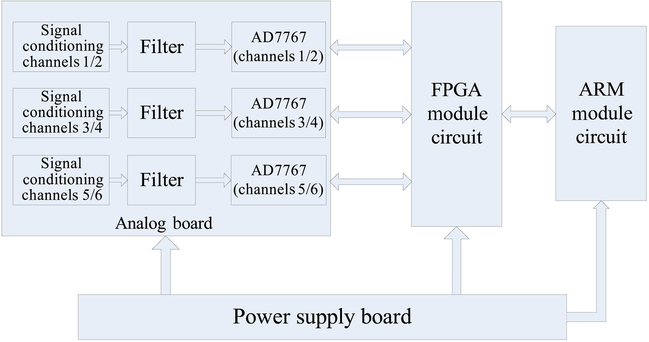
The receiving system consists of four parts, namely a field programmable gate array (FPGA) unit, an advanced reduced instruction set computer (RISC) machine (ARM) unit, an analog acquisition unit, and a power supply circuit. The system block diagram is shown in Fig. 1. The numbers of analog boards are marked as channels 1∕2, 3∕4, and 5∕6, and each board has two channels. The board contains the signal-conditioning circuit and channels for amplification and acquisition, which are completely independent. Hence, multichannel real-time synchronized acquisition is achieved.
2.2 Design of analog circuit board
The analog board mainly includes the signal conditioner (including the first-stage instrumentation amplifier, the second-stage programmable amplifier, and a low-pass filter), a protection circuit (input stage clamp diode), the natural potential compensation circuit (Liu et al., 2016), a single-ended-to-differential circuit, and an analog-to-digital converter.
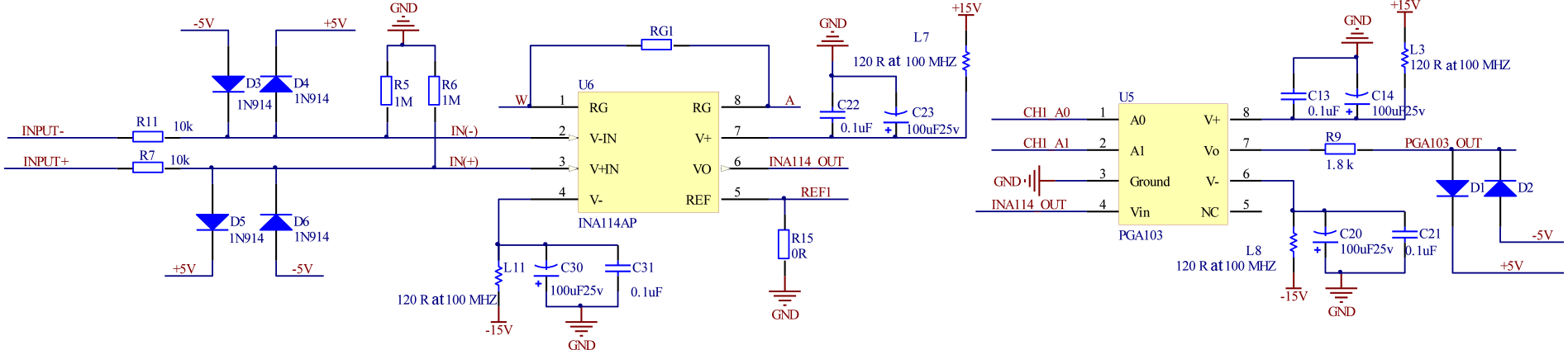
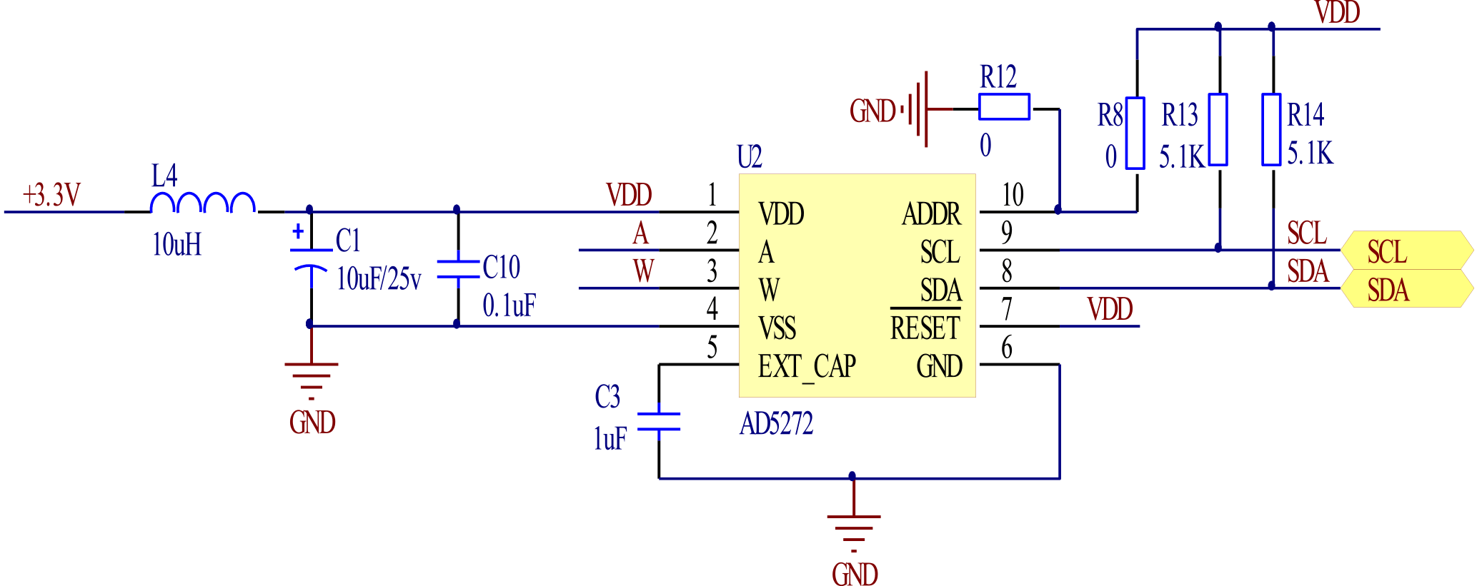
The first-stage amplifier uses a dedicated high-precision, low-noise amplifier INA114, and a high-resolution digital potentiometer AD5272 is used to design the precision gain op-amp to achieve high-precision amplification and range adjustment. The two circuits are shown in Figs. 2 and 3.
In Fig. 2, the circuit utilizes the programmable gain amplifier PGA103 and a general input and output (IO) port to complete the three-level amplification ratio adjustment.
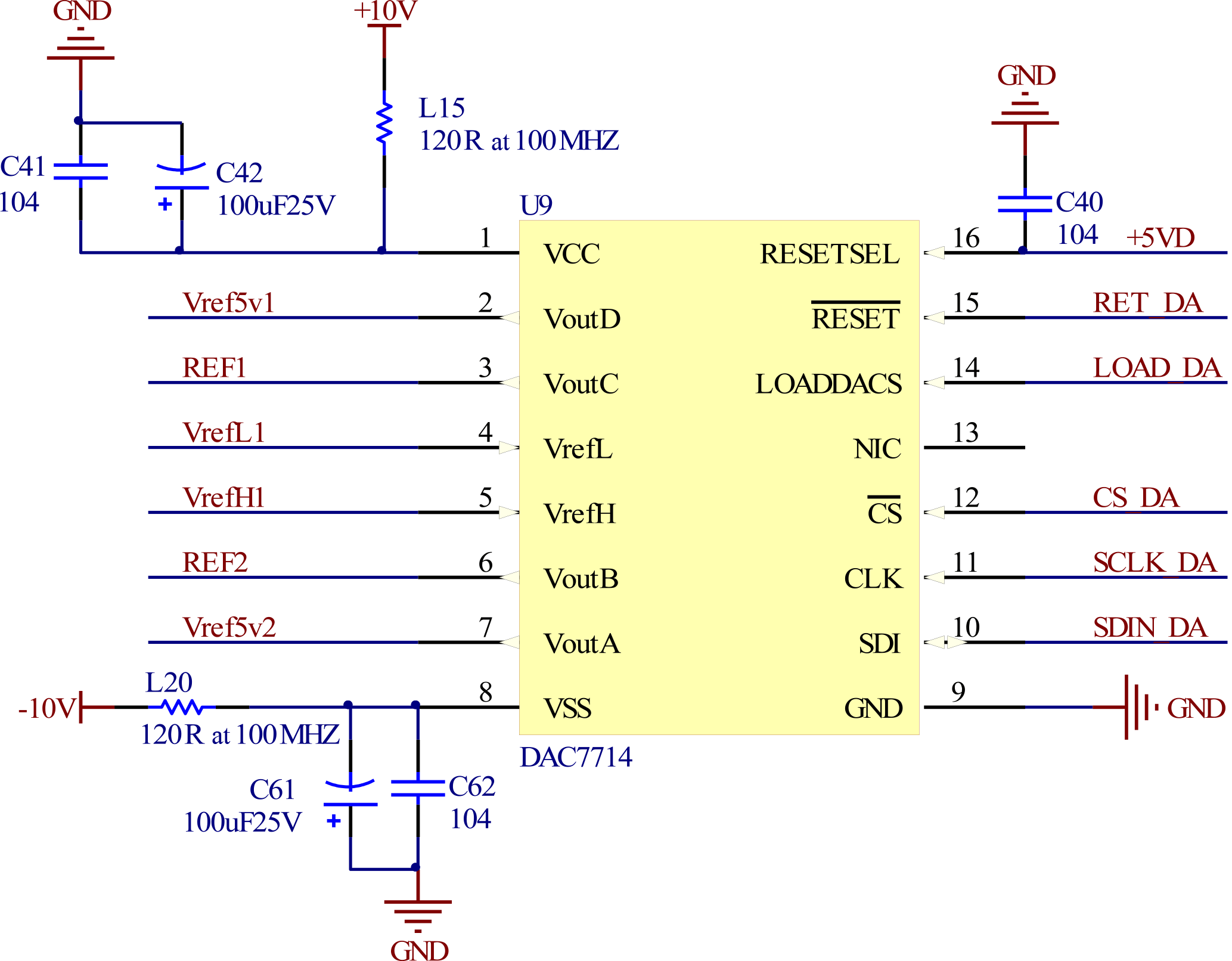
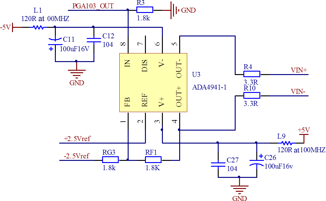
Two natural potential compensation voltages and two full-scale reference voltages are supplied by DAC7714, a 12 bit digital-to-analog converter with four output channels. The DAC7714 circuit is shown in Fig. 4. The multichannel receiver has a wide input voltage range, which varies from −5 to +5 V, and the amplitude of the signals actually collected is from dozens to hundreds of millivolts.
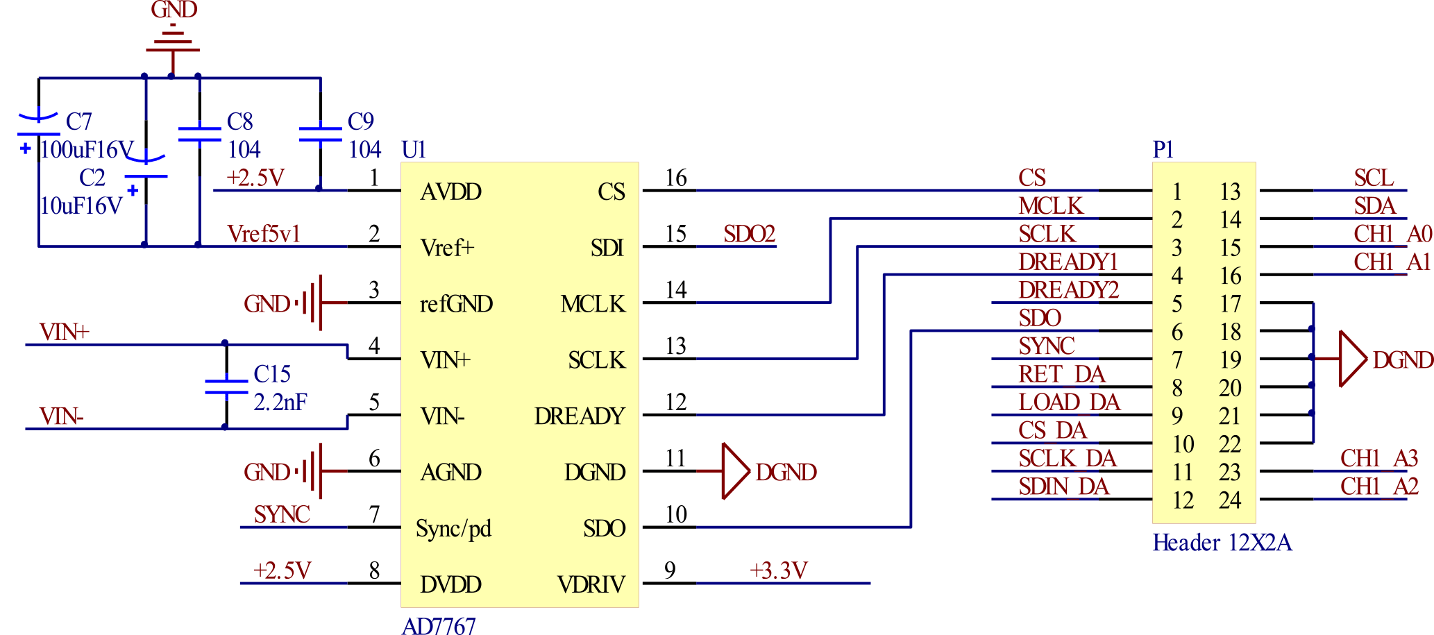
ADA4941 is a single-ended-to-differential converter that is used as the front part of an analog-to-digital converter. Each channel of the receiver uses a separate AD7767, a 24 bit high-resolution and wide dynamic-range converter. The AD7767 is a ADC with oversampling characteristics, which can reduce noise from the front end and the need for a front-end anti-alias filter, and uses its daisy chain technology to realize the multi-chip cascade connection for an efficient parallel synchronous acquisition method (Liu et al., 2017). These two circuits are shown in Figs. 5 and 6.
By adopting a modular design, two AD7767 chips are cascaded, and an FPGA controller is used to control the three analog circuit boards separately, and therefore the overall data packaging and storage in real time is achieved. The AD7767 chip has a maximum output data rate of 128 kHz, so the bandwidth of the receiver ranges from direct current (DC) to 12.8 kHz. For a good accuracy of collection, the frequency of the input signal should be less than 12.8 kHz.
2.3 Design of the digital logic controller board
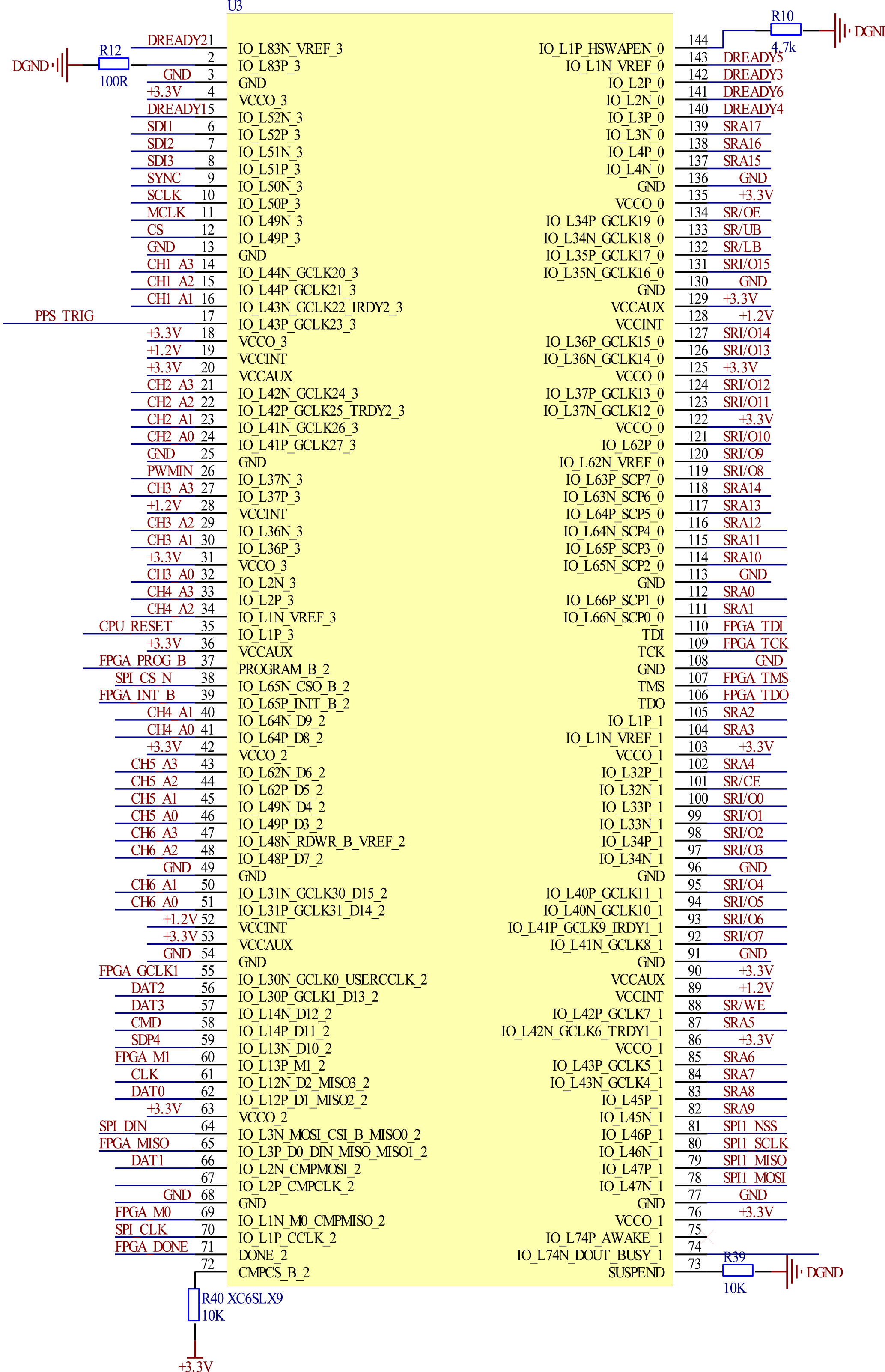
The multichannel synchronous receiver is made up of an embedded controller and an FPGA controller (Oballe-Peinado et al., 2017), which is flexible and widely used. The FPGA is the core controller of the receiving system, and the synchronization between the various functional units can be easily achieved by its parallel processing function; therefore, a number of logic modules are driven by the same clock source. This receiver uses an XC6SLX9 chip as the core acquisition controller, that belongs to the Spartan-6 series of the well-known FPGA chip maker Xilinx. It is shown in Fig. 7. The FPGA unit is mainly composed of an SD card unit circuit, static random access memory (SRAM) buffer circuit, and the serial peripheral interface (SPI) which is used to communicate with the STM32 controller, the synchronous signal acquisition and control interface of six channels, and GPS's pulse per second (PPS) signal interface and power interface.
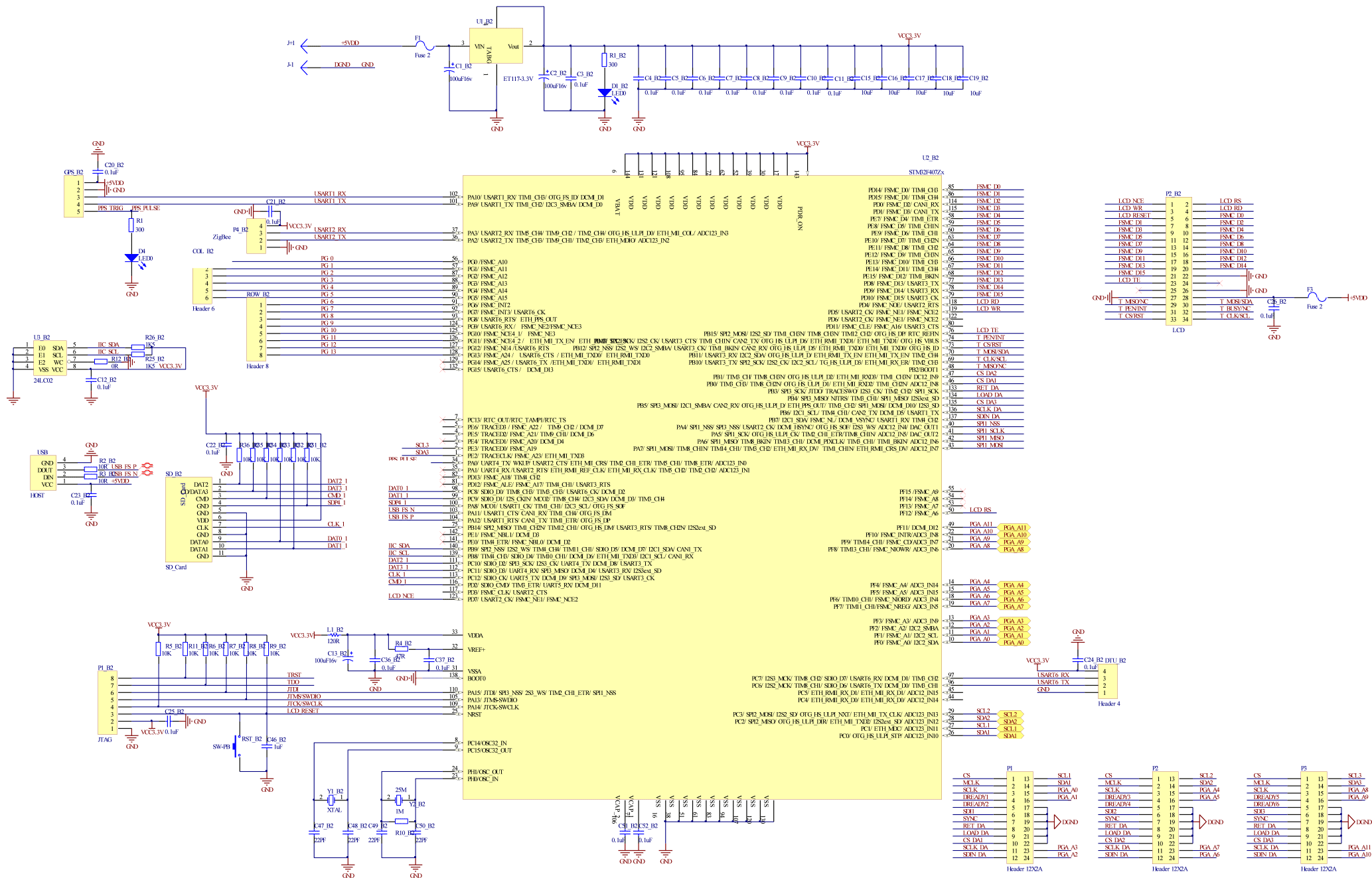
The STM32F4 series of ST Microelectronics is adopted as controller unit which is popular in industry and instrumentation. The embedded controller unit has the following functions: keyboard input, communication with the FPGA, GPS location information collection, and a liquid crystal display (LCD). The collected GPS information is composed of latitude, longitude, time, and so on, which is output by the GPS module through the serial port and simultaneously displayed on a LCD. A 6×8 matrix keyboard is designed to set the system parameters and select the channel for data collection. When the GPS satellite signal is locked, the receiving system can collect the data according to the preset instruction by a start key. A general-purpose IO port is used to control the DAC7714 chip to achieve natural potential compensation, reference voltage, and fine gain tuning. The STM32F407 diagram is shown in Fig. 8.

2.4 High-precision linear power circuit
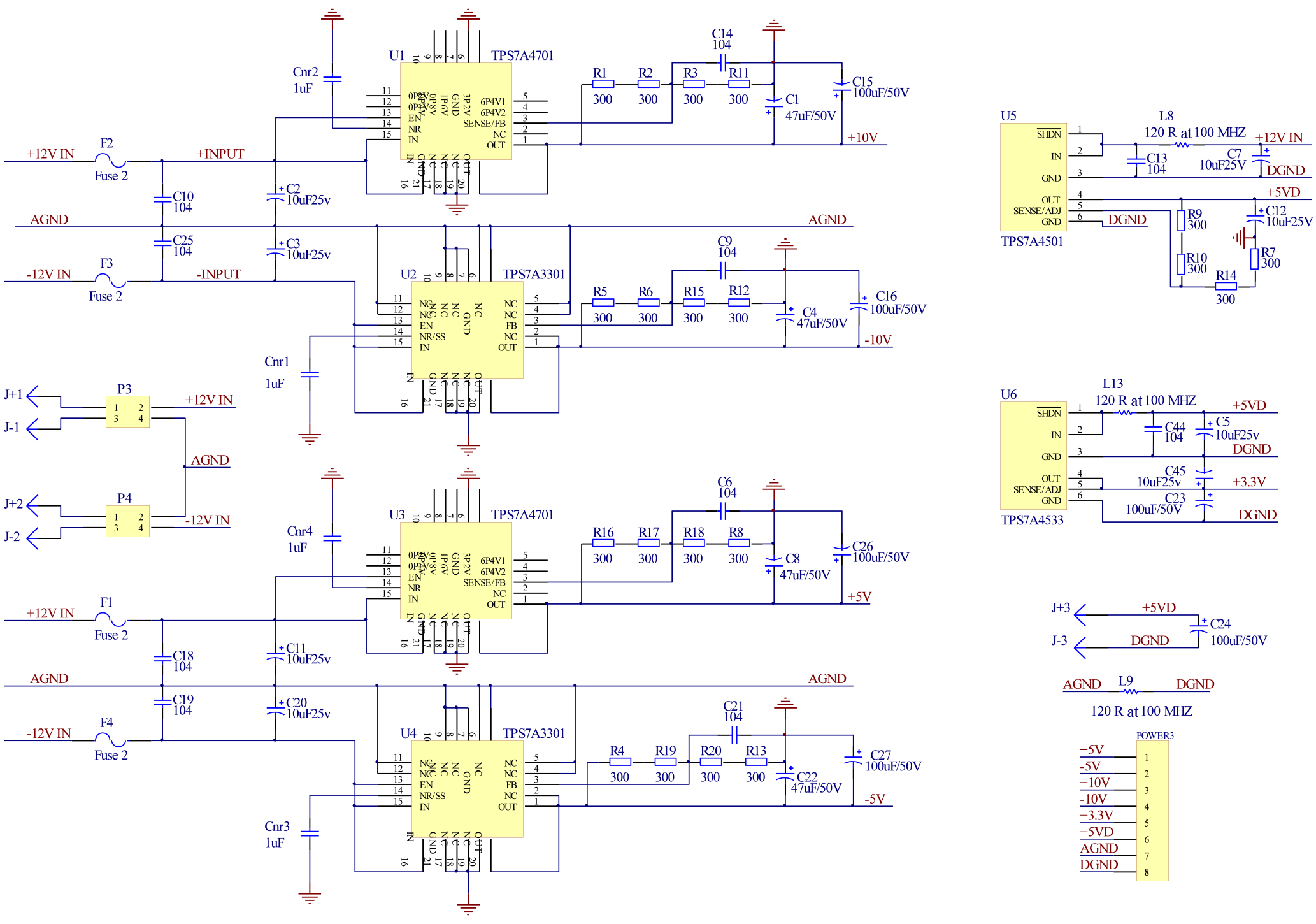
Low-dropout–output linear power chips with a high-precision and a high ripple rejection ratio are selected (Joo et al., 2017; Duong et al., 2017). On the power board, there are three independent connecting plugs connecting each analog board (Ren et al., 2015). In the receiver, the TPS7A series chips are selected, which are manufactured by the Texas Instrument company. These chips have the following characteristics: a wide input voltage range, low noise, and a high ripple rejection ratio. The power board has four different output voltages (+10, −10, +5, and −5V), which are used for preamplifiers and the programable gain amplifier (PGA). Another separate +5V power supply for the digital potentiometer on the analog board and the DAC7714 chip and 3.3 V power provide digital logic power for the analog-to-digital converter AD7767 (Yun et al., 2017). The power diagram is shown in Fig. 9. Since all chips are low-powered, the overall power consumption of the receiver is less than 10 W.

2.5 Software design
The software mainly includes two parts: (1) the program of the FPGA unit, which involves the data storage on an SD card, real-time communication with STM32, data processing in data buffer area, and so on; (2) the program of the STM32 unit, which includes the gain adjustment of the first-stage preamplifier, the ratio setting of the second-stage programmable amplifier, and natural potential compensation control (Khomutov et al., 2017).
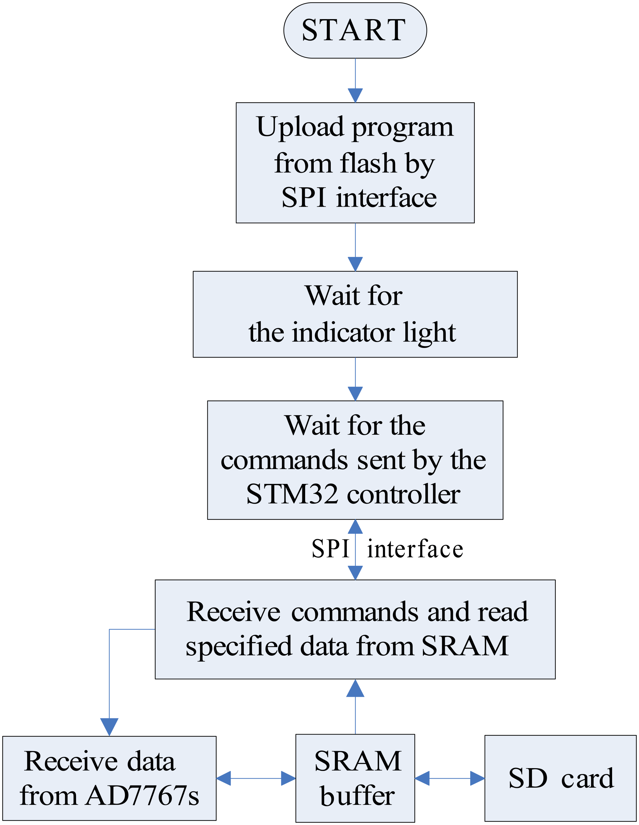
The FPGA mainly controls the front-end analog-to-digital converter, data storage, and interactions with STM32 by SPI. First, the FPGA controller loads the program from flash after power-on and then waits for the operation control commands sent from STM32, such as system initialization, parameter setting, and sensor calibration (Wang et al., 2017). Time information and the channel serial number are stored on an SD card through the FPGA program. The information is stored in the first 8 bytes in each sector of the SD card. The PPS provided by the GPS unit is used to update the internal base time of the FPGA every 2 s. It can reduce the time cumulative error.
The embedded controller is responsible for coordinating the operation of the entire system, such as the system gain adjustment of each channel, GPS time information reception and status monitoring, and real-time display of acquired data, and communicating with the FPGA controller (X. Y. Zhang et al., 2017). The system flowchart is shown in Fig. 10.

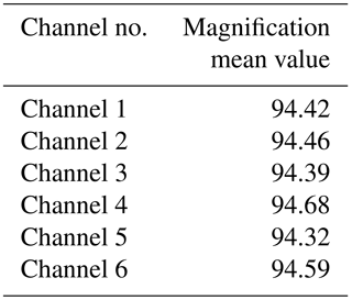
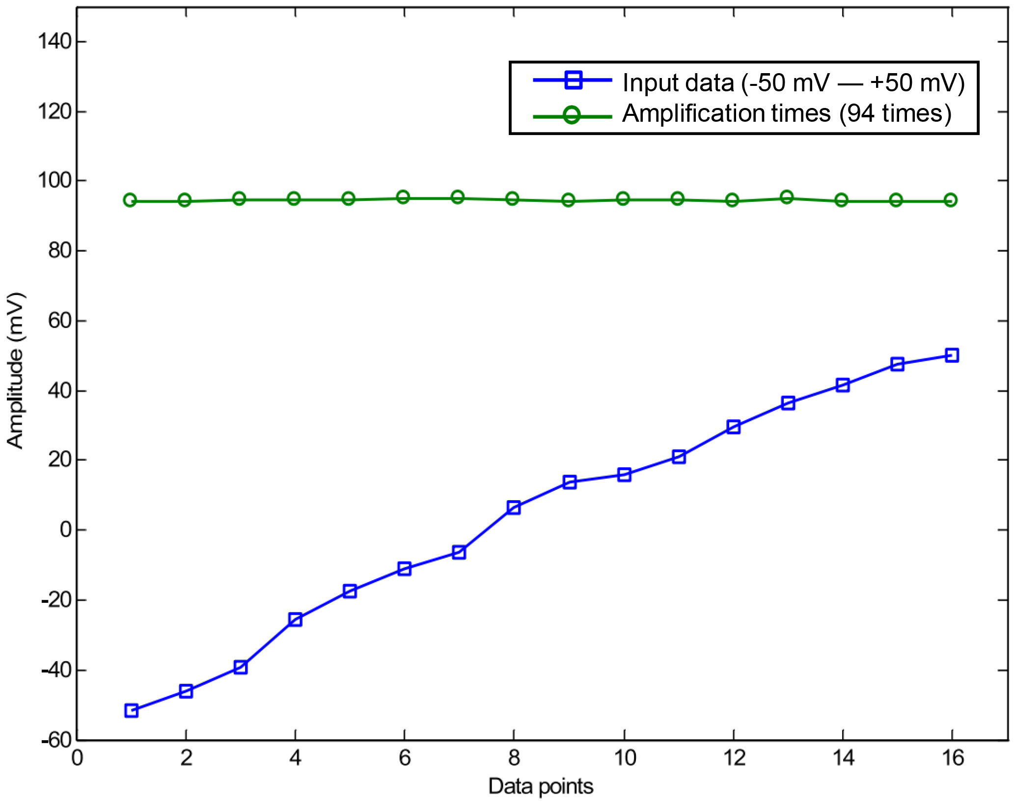
Performance testing of the receiver system mainly includes DC testing, AC testing, and field testing (Ziolkowski et al., 2010; Zhou et al., 2015). In the DC stability testing, we first tested the magnification range of each channel and the magnification consistency. Taking the first channel as an example, as is shown in Fig. 11 below, the input signal is a blue curve with a range of ±50mV. The green curve is the magnification times of the first channel when each data value of input signal was calculated. Under the same test conditions, the six channels were connected in parallel, and the same input signals were received separately by six channels at the same time. The average magnification times of each channel are shown in Table 1.
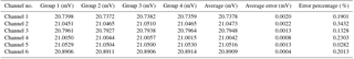
Next was the conformance test for channels of the receiver. The test aimed to confirm high consistency between channels. In the test, the positive terminals of the six channels were connected together as a positive port, while negative terminals were linked to each other as a negative port. The two ports were input with standard sine waves. The peak-to-peak voltage value of input signal was 20 mV and its frequency was 150 Hz. The extracted numerical values of each channel at the same time were compared to obtain the average error, the average absolute error, and error percentage, as is shown in Table 2. The average error is less than 2.2 µV.
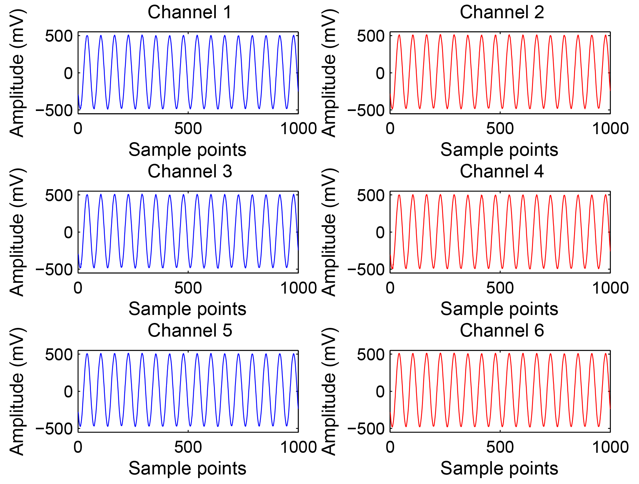
In the AC testing, the six channels of the positive and negative terminals were connected separately, and the sine waves generated by a standard signal generator were input to the receiver. The waveforms generated by the collected data are shown in Fig. 12. The peak-to-peak value of the input signal was 10 mV, and its frequency was 20 Hz. As can be seen from the figure, the consistency between each channel is quite high and there is no phase offset. After the input signals are amplified by a two-stage amplifier in the analog board, the output peak-to-peak value of each channel is up to 1000 mV.
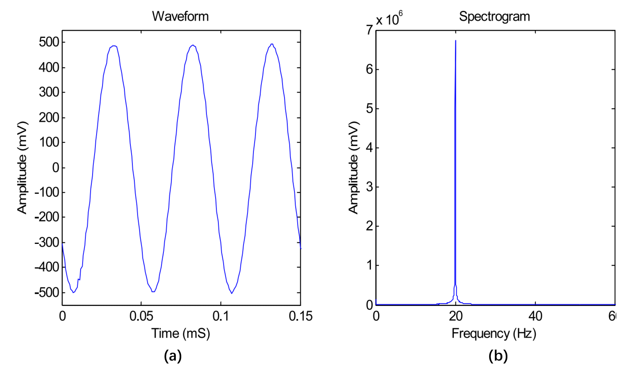
Figure 13a shows the waveform of three cycles of data acquired by the first channel shown in Fig. 12. Figure 13b presents the frequency spectrum formed by fast Fourier transform (FFT). As is shown in Fig. 13b, the frequency of the input sine waves is 20 Hz, and the frequency spectrum has few harmonic components, which indicates the excellent performance of the analog circuit board and the high stability of the power circuit.
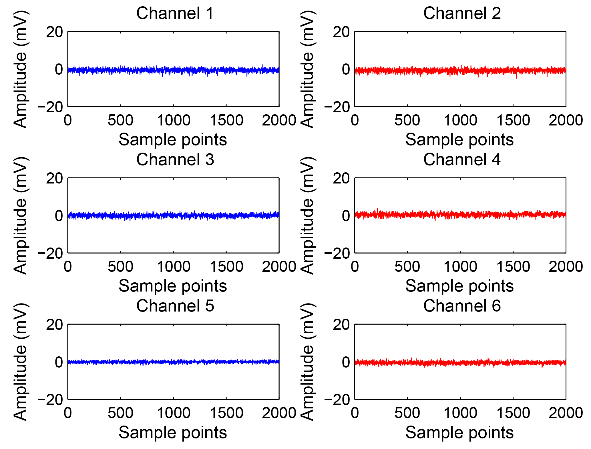
In Fig. 14, when six channels are connected to zero voltage in the same way, 2000 data points of each channel are displayed. According to Eq. (1), the SNR of each channel is calculated to be approximately 100 dB.
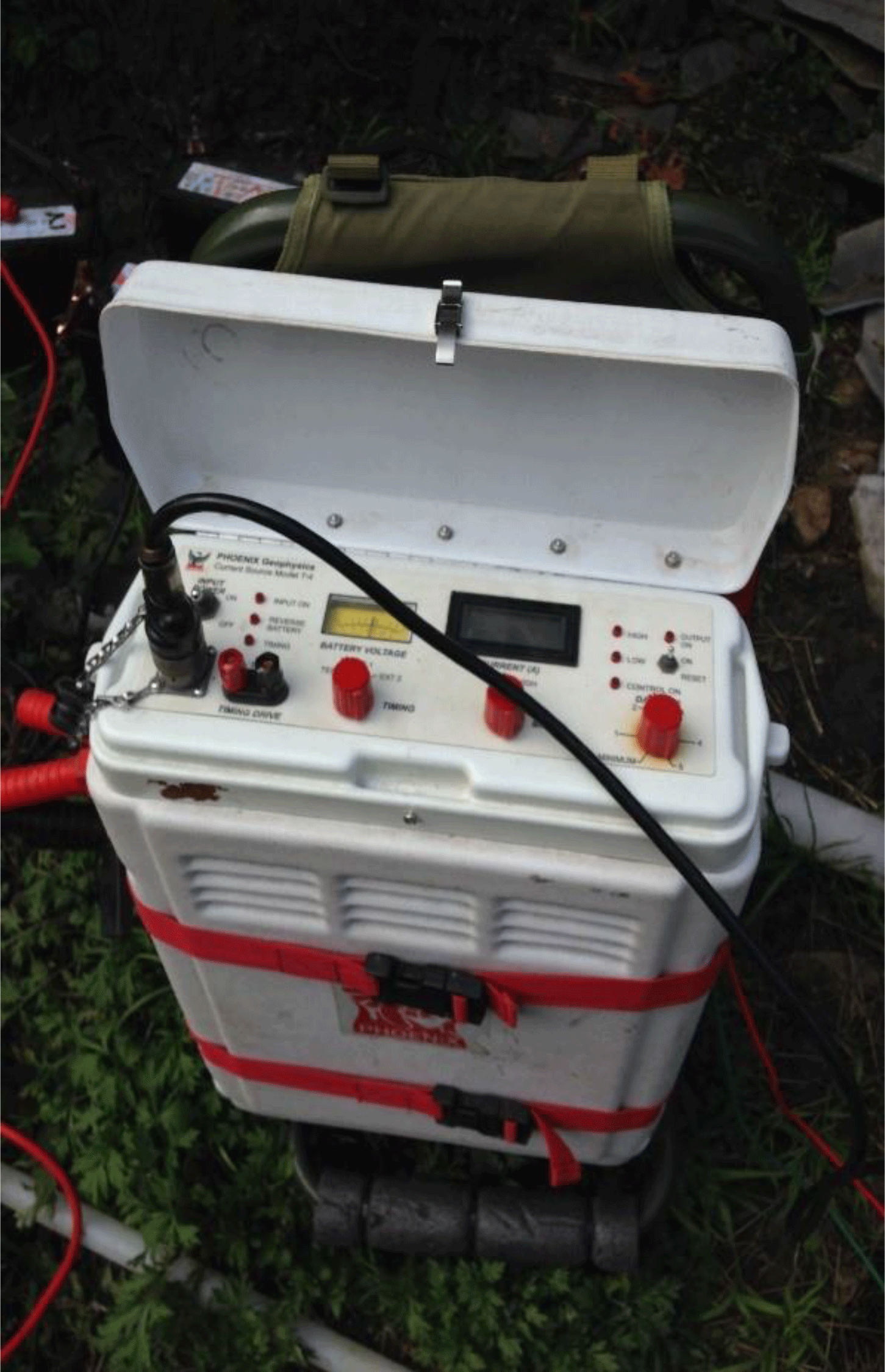
In field testing, a hollow coil with 400 turns and a diameter of 50 cm was used as the receiving sensor (Brunke et al., 2017), and its effective area is 40 m2. Phoenix T-4 transmitter is a small power transmitter, which is manufactured by Phoenix. This transmitter can launch up to 40 A currents, powered by a battery group, and it can launch many kinds of waveforms, such as TD50 (numbered by Phoenix), which is a bipolar pulse waveform with a 50 % duty cycle (Wang et al., 2015) and was used in the actual test. The V8 system is the eighth generation of receiver technology developed by Phoenix since 1975. The V8 sampling rate is 96 000, and its flash memory capacity is 512 MB only. It cannot store all received data and is synchronized by a GPS unit. However, the sampling rate of the multichannel TEM receiver is 128 000 SPS, and the synchronization mechanism is realized by GPS and a 28 bit high-precision counter. The accuracy of synchronization can be improved, and all the time information and collected data are stored on an SD card simultaneously.
Two sites were selected for field testing, one of which is a relatively open area; the other is the actual mining area. The near-field measurement method was used in the test. A grounded electrode source was adopted as the field source. Four aluminum plates were used as electrodes, which were linked together and buried 40 cm deep in the ground and covered with saltwater and soil, so that the grounding resistance was less than 10 Ω. The distance between the transmitting electrodes A and B was 400 m, and four batteries were used as the power supply. The voltage ranged between 40 and 50 V. The emission current was 3 A, and the emitting frequency was 25 Hz.
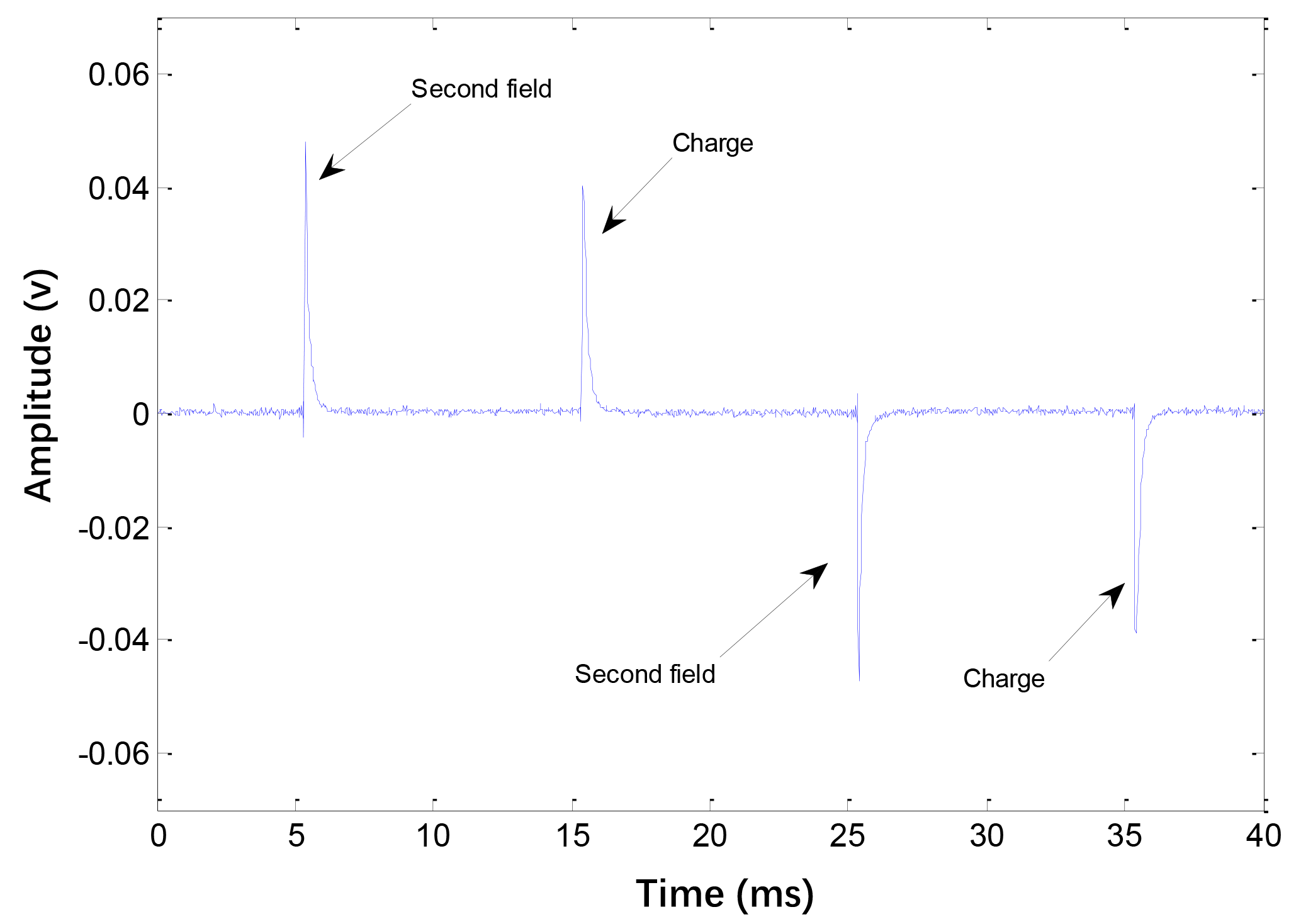
During the test, the power supply electrodes were stationary, while the preset measurement line was parallel with the transmitting line. The offset between transmitting line and receiving line was 40 m. The changing rate of the magnetic flux density (dB ∕ dt) was received by the coil. Figure 15 below shows one original cycle.
The open area where the test was carried out is formed by the mixture of soil and building slag. The measurement line was observed at eight measuring points. After the data was stored, data of the eight collecting points were processed by a MATLAB computer program. Then, the secondary field information of each testing point was extracted. The resulting profile curve was formed.
Figure 16 shows the profile, which is formed by the extracted data and indicates that the overall response tends to be flat. The signals received at the measurement points close to the transmitting nodes are relatively strong, while the central part of the profile becomes flat slowly.
In order to test the performance of the receiver further, a mining area in Leshan, Sichuan Province, China, was selected for the field test, and a relatively gentle geodetic survey line was planned. The electrode source emission was adopted, and the distance between the transmitting electrodes was 400 m. The testing line offset was 80 m, and the distance between the measuring points was 40 m.
A continuous launch mode was used in a mining area test, and the transmitting frequency of the signal was 25 Hz. A multichannel synchronous transient electromagnetic receiver can be used to collect the data of the transmitting current waveform, the change rate of the magnetic field, and the intensity of the electric field.
Figure 17 is composed of three sub-figures in the mining area. Figure 17a shows the change rate of the magnetic field (dB ∕ dt), and Fig. 17b presents electric field intensity; Fig. 17c is about the transmitting current waveform. All sub-figures display two periods of signals (80 ms). Figure 17a and b were formed from data acquired by a receiver, and Fig. 17c was formed from data acquired by another receiver. The high-precision synchronization mechanism is implemented with a high-reliability GPS module and a 28 bit counter in the FPGA. The receiver's time information is refreshed every 2 s by the PPS of the GPS module. The 28 bit counter is used to record the pulses, which come from a 25 MHz clock in an FPGA chip. The 28 bit counter value, time information, and data collected by the receiver are packaged and stored on an SD card. The time error between every two points is 40 ns according to the period of the 25 MHz clock and the frequency of refreshment. Each collected sample can be tracked by the stored time information and data information on an SD card. The full-time range storage technology can greatly enhance the synchronization accuracy, even with many receivers working at the same time in the mining area.
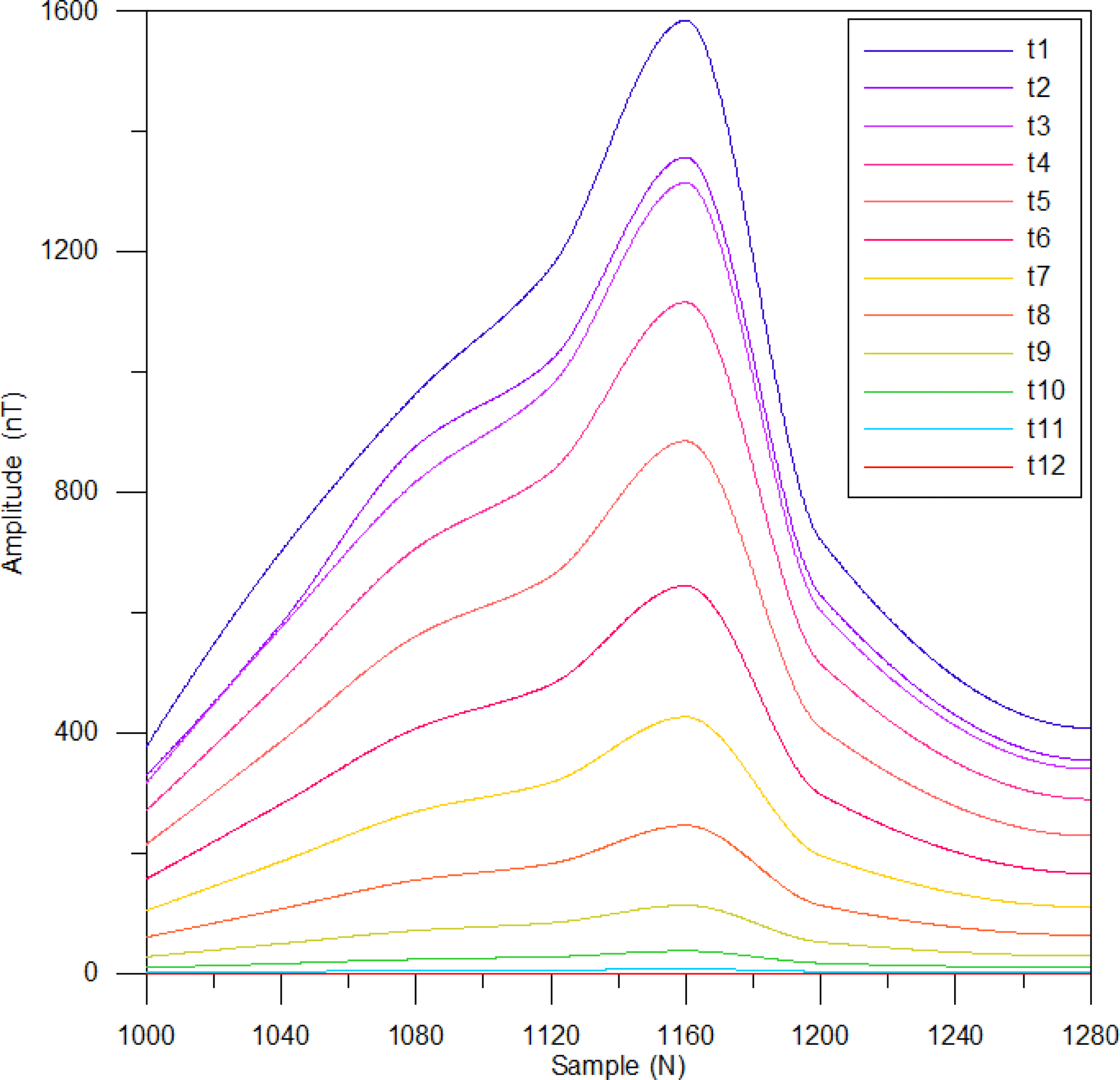
The acquired data in the mining area were second-field extracted, filtered, and interpolated, and the waveform was formed. The waveform of the time domain is smoother after waveforms were superimposed 200 times, which can reflect the response of underground geological bodies to TEM well. The data of each measuring point were processed to obtain the pure secondary field curves, and the time domain waveforms were extracted to form the profile of the measuring line. In Fig. 18, t1–t12 represent the extraction time (Zhong et al., 2016), and the extracted values of different collection points were collected together to form 12 curves at different time points.
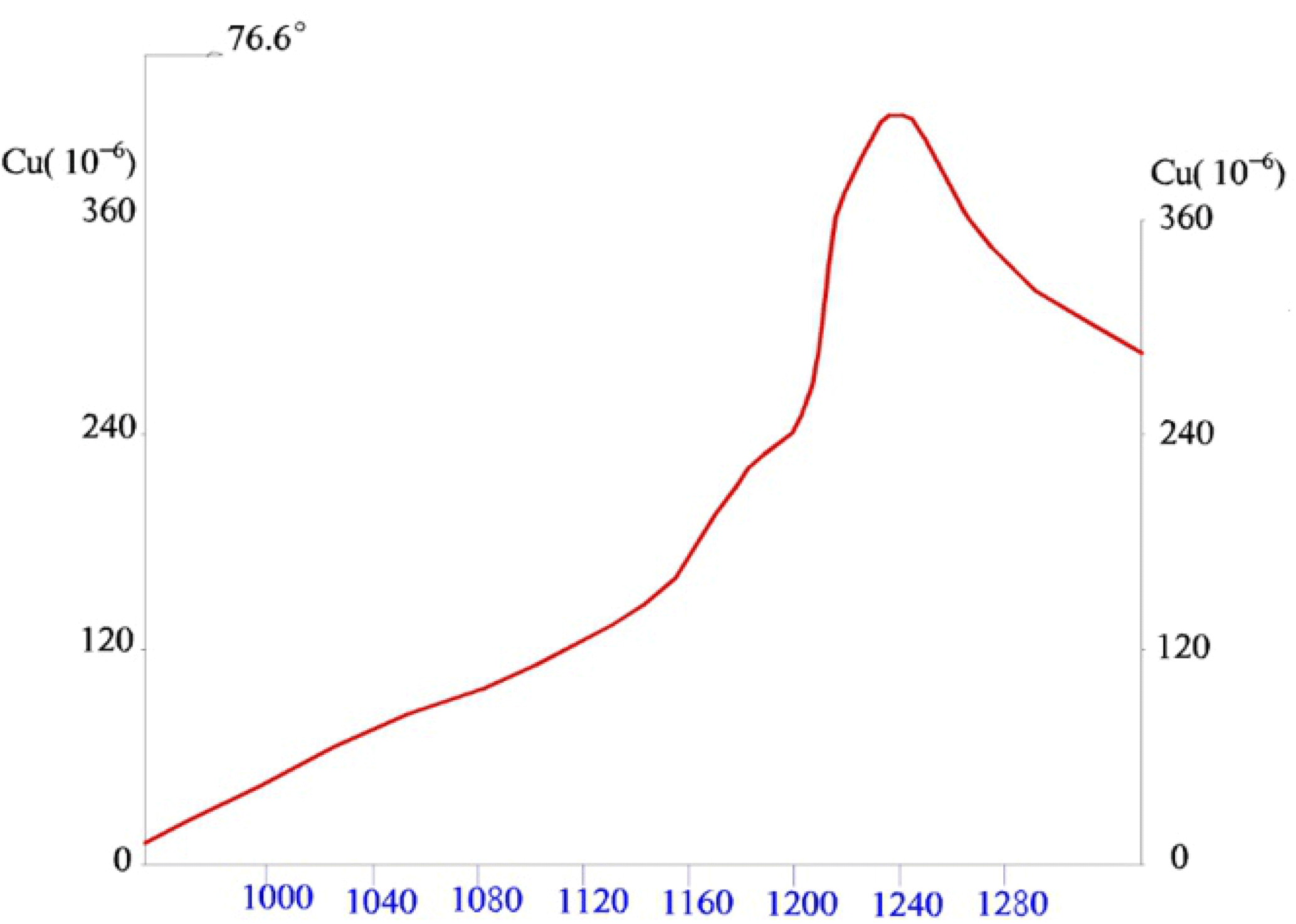
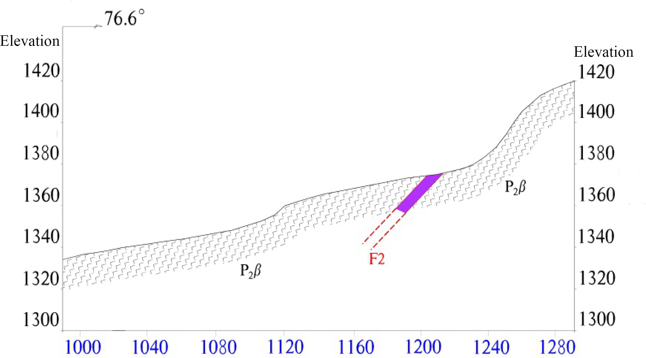
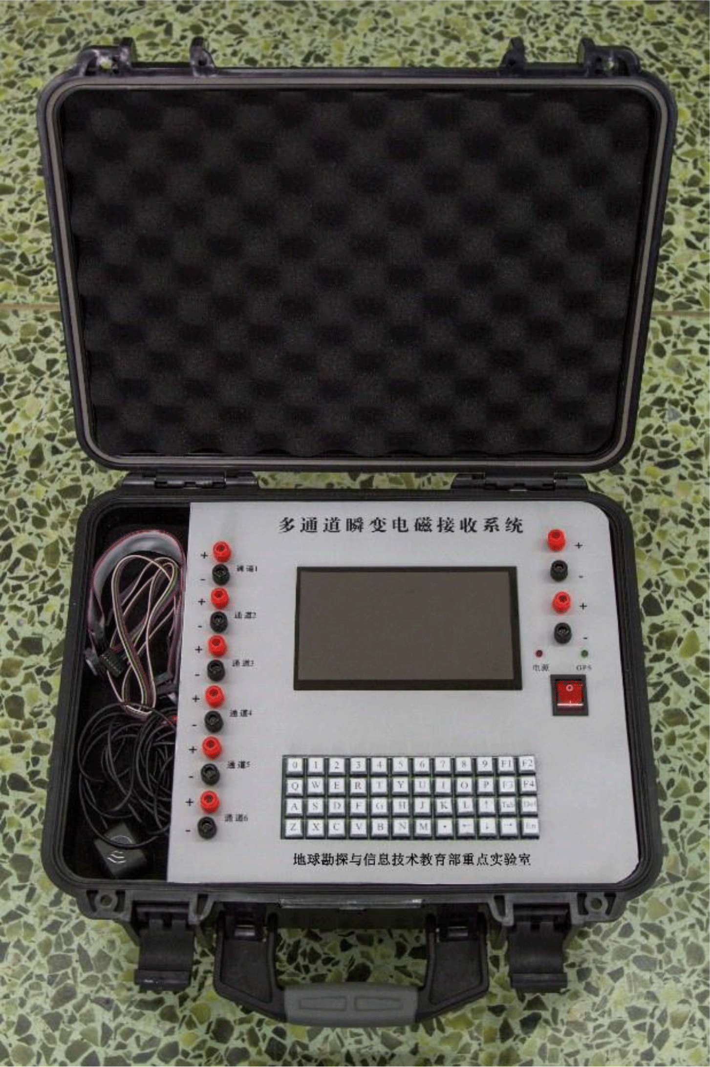
As can be seen by comparing Figs. 19 and 20 with Fig. 18, the high anomaly point is near Point 1160, which happens to be a sloped metal vein. Thus, it is verified that the receiver can acquire signals of transient electromagnetic emission very well. By analyzing and comparing the profile with the actual geochemical distribution, it can obviously be seen that the abnormality of the curves is highly consistent at Point 1160. In addition, the anomaly is consistent with the geological structure in this area. Figure 21 is the receiver photo, and Fig. 22 shows the T4 transmitter working at the testing field, and Fig. 23 is the map of mining area.
The purpose of this paper is to develop the multichannel synchronous receiver that can be applied in transient electromagnetic prospecting. First, the hardware circuits and software programs were designed to realize the functions mentioned above. By means of a dual controller, the receiver can acquire signals synchronously through six independent channels. Then, the data stored on an SD card were processed by computer programs to generate profile graphs. The overall performance of the receiver was tested and verified. All the collected data error of each channel is less than 0.35 %, and each channel can connect different sensors, such as coils, magnetic probes, and electrodes. The receiver can be used to collect transient electromagnetic information. Due to its high precision and high sampling rate, it can capture the fast falling edge of TEM and ultralow noise and so on. Hence, by adopting the receiver, the multichannel synchronous acquisition of magnetic field information in three directions, electric field information in two directions, and the changing rate of magnetic induction intensity can be realized in the time domain reception.
In addition, the reliability, practicability, and data validity of the receiver were verified by field testing in the mining area. Meanwhile, the receiver can be used for pseudorandom signal reception and distributed three-dimensional data reception, which can improve geophysical exploration efficiency.
The codes of the receiver are available upon request (linfq@cdut.edu.cn).
The circuit schematics of the receiver are available upon request (linfq@cdut.edu.cn).
FQ developed the main hardware and part of the software, and XB instructed all the authors. The other authors participated in the experiments and software development.
The authors declare that they have no conflict of interest.
This work was supported by the national key research and development project
(no. 2016YFC0600300), the National Natural Science Foundation of China
(no. 41674078), and the Field observation and research base of the Ministry of Land
and Resources of China for Geohazards in the earthquake-disturbed area of the Longmen
Mountains in Chengdu.
Edited by: Luis
Vazquez
Reviewed by: Taifei Zhao and one anonymous referee
Ayuso, S., Blanco, J. J., Medina, J., Gomez-Herrero, R., Garcia-Poblacion, O., and Gracia, T. I.: A coincidence detection system based on real-time software, Geosci. Instrum. Meth., 2, 1–36, https://doi.org/10.5194/gi-5-437-2016, 2016.
Brunke, H. P., Widmer-Schnidrig, R., and Korte, M.: Merging fluxgate and induction coil data to produce low-noise geomagnetic observatory data meeting the INTERMAGNET definitive 1 s data standard, Geosci. Instrum. Meth.,2, 487–493, https://doi.org/10.5194/gi-6-487-2017, 2017.
Chen, W. Y., Khan, M. Y., Xue, G. Q., Cui, J. W., and Zhong, H. S.: Study on the response and optimal observation area for SOTEM, Chinese J. Geophys.-Ch., 2, 739–748, https://doi.org/10.6038/cjg20160231, 2016.
Chen, W. Y., Khan, M. Y., and Xue, G. Q.: Response of surface-to-borehole SOTEM method on 2D earth, J. Geophys. Eng., 3, 987–997, https://doi.org/10.1088/1742-2140/aa6fcc, 2017.
Danielsen, J. E., Auken, E., Jørgensen, F., Søndergaard, V., and Sørensen, K. I.: The application of the transient electromagnetic method in hydrogeophysical surveys, J. Appl. Geophys., 53, 181–198, https://doi.org/10.1016/j.jappgeo.2003.08.004, 2003.
Duong, Q. H., Nguyen, H. H., Kong, J. w., Shin, H. S., Ko, Y. S., Yu, H. Y., Lee, Y. H., Bea, C. H., and Park, H. J.: Multiple-Loop Design Technique for High-Performance Low-Dropout Regulator, IEEE J. Solid-St. Circ., 10, 2533–2549, https://doi.org/10.1109/JSSC.2017.2717922, 2017.
Haroon, A., Adrian, J., Bergers, R., Gurk, M., Tezkan, B., Mammadov, A. L., and Novruzov, A. G.: Joint inversion of long-offset and central-loop transient electromagnetic data: Application to a mud volcano exploration in Perekishkul, Azerbaijan, Geophys. Prospecting, 63, 478–494, 2015.
Li, W. Y., Yan, C. W., Zou, Z. W., and Wang, R. H.: Research progress of transient electromagnetic apparatus, Journal of YunNan University (natural science edition), 34, 233–241, 2012.
Liu, H., Wang, W. D., Xiang, C. L., Han, L. J., and Nie, H. Z.: A de-noising method using the improved wavelet threshold function based on noise variance estimation, Mechanical System and Signal Processing, 99, 30–46, doi:10.1016/j.ymssp, 2017.
Liu, J. N., Ai, W., Wen, F., and Liu, D. H.: Design of Cascaded Multi-channel Signal Isolated Acquisition Circuit, Instrument Technique and Sensor, 12, 148–151, 2016.
Joo, S. and Kim, S.: PSR enhancement techniques for output-capacitor-free LDO regulator design, Analog Integrated Circuits and signal Processing, 2, 319–327, https://doi.org/10.1007/s10470-017-1045-9, 2017.
Khomutov, S. Y., Mandrikova, O. V., Budilova, E. A., Arora, K., and Manjula, L.: Noise in raw data from magnetic observatories, Geosci. Instrum. Meth., 2, 329–343, https://doi.org/10.5194/gi-6-329-2017, 2017.
KMS: KMS-820, http://www.kmstechnologies.com, last access: 1 January 2017.
Metronix: ADU-07e, https://www.metronix.de/metronixweb, last access: 1 January 2017.
Oballe-Peinado, O., Hidalgo-Lopez, J. A., Castellanos-Ramos, J., Sanchez-Duran, J. A., Navas-Gonzalez, R., Herran, J., and Vidal-Verdu, F.: FPGA-Based Tactile Sensor Suite Electronics for Real-Time Embedded Processing, IEEE T. Ind. Electron., 12, 9657–9665, https://doi.org/10.1109/TIE.2017.2714137, 2017.
Phoenix Geophysics: V8 receiver, http://www.phoenix-geophysics.com/products/receivers/v8/, last access: 1 January 2017.
Qi, Y. F., Yin, C. C., Wang, R., and Cai, J.: Mutlti-Transient EM full-time forword modeling and inversion of m-sequences, Chinese J. Geophys., 7, 2566–2577, https://doi.org/10.6038/cjg20150731, 2015.
Ren, Z. D., Guo, C. S., and Lin, P. F.: Design of High-Performance LDO with Buffer Impedance Attenuation, Microelectronics, 2, 225–227, 2015.
Wang, H. F., Chen, S. D., Zhang, S. Yuan, Z. W., Zhang, H. Y., Fang, D., and Zhu, J.: A High-Performance Portable Transient Electro-Magnetic Sensor for Unexploded Ordnance Detection, Sensors Basel, Switzerland, 11, 2651–2668, https://doi.org/10.3390/s17112651, 2017.
Wang, X. L., Gao, J. X., Tian, J. S., and Zhang, Y. T.: Design of power transformer in MTEM transmitter power, Atlantis Press, International Conference on Civil, Materials and Environmental Sciences (CMES 2015), 161–164, https://doi.org/10.2991/cmes-15.2015.47, 2015.
Wright, D.: Detection of hydrocarbons and their movement in a reservoir using time-lapse Multichannel Transient ElectroMagnetic data [D], Edinburgh, University of Edinburgh, 2004.
Xue, G. Q., Chen, W. Y., Zhou, N. N., and Li, H.: Short offset TEM technique with a grounded wire source for deep sounding, Chinese J. Geophys., 1, 255–261, https://doi.org/10.6038/cjg20130126, 2013.
Yun, S. J., Kim, J. S., and Kim, Y. S.: Capless LDO Regulator Achieving-76 dB PSR and 96.3 fs FOM, IEEE T. Circuits Syst., 10, 1147–1151, https://doi.org/10.1109/TCSII.2016.2628965, 2017.
Zhang, X. H., Du, J. L., Fan, C. G., Liu, D, Fang, J. L., and Wang, L. S.: A Wireless Sensor Monitoring Node Based on Automatic Tracking Solar-Powered Panel for Paddy Field Environment, IEEE Internet Things, 5, 1304–1311, https://doi.org/10.1109/JIOT.2017.2706418, 2017.
Zhang, X. Y., Zhang, Q. S., Wang, M., Kong, Q., Zhang, S. Q., He, R. H., Liu, S. H., Li, S. H., and Yuan, Z. Z.: Development of a full-waveform voltage and current recording device for multichannel transient electromagnetic transmitters, Geosci. Instrum. Meth., 2, 495–503, https://doi.org/10.5194/gi-6-495, 2017.
Zhong, H. S., Xue, G. Q., Li, X., Zhi, Q. Q., and Di, Q. Y.: Pseudo wave field extraction in the multi-channel transient electromagnetic (MTEM) method, Chinese J. Geophys., 59, 4424–4431, 2016.
Zhou, N. N., Xue, G. Q., Chen, W. Y., and Chen, J. L.: Large-depth hydrogeological detection in the North China-type coalfield through short-offset grounded-wire TEM, Environ. Earth Sci., 3, 2393–22404, https://doi.org/10.1007/s12665-015-4240-y, 2015.
Ziolkowski, A., Parr, R., Wright, D., Nockles, V., Limond, C., Morris, E., and Linfoot, J.: Multi-transient electromagnetic repeatability experiment over the North Sea Harding field, Geophys. Prospect., 58, 1159–1176, 2010.