the Creative Commons Attribution 4.0 License.
the Creative Commons Attribution 4.0 License.
 | 26 Feb 2021
A new borehole electromagnetic receiver developed for controlled-source electromagnetic methods
Sixuan Song
Ming Deng
Kai Chen
Muer A
Sheng Jin
Conventional surface electromagnetic methods have limitations of a shallow detection depth and low resolution. To increase the detection depth and resolution, borehole–surface electromagnetic methods for electromagnetic three-dimensional observations of the ground, tunnels, and boreholes have been developed. Current borehole receivers only measure a single parameter of the magnetic field component, which does not meet the special requirements of controlled-source electromagnetic (CSEM) methods. This study proposes a borehole electromagnetic receiver that realizes synchronous acquisition of the vertical electric field component in the borehole and the three-axis orthogonal magnetic field components. This receiver uses Ti electrodes and fluxgate magnetometers (fluxgates) as sensors to acquire electric and magnetic field components. Multi-component comprehensive observation methods that add the electric field component can effectively support the CSEM method, improve detection accuracy, and exhibit a strong potential for detecting deep ore bodies. We conducted laboratory and field experiments to verify the performance of our new borehole electromagnetic receiver. The receiver achieved a magnetic field noise of less than 6 at 1 kHz, and the electric field noise floor was approximately 20 at 1 kHz. The −3 dB electric field bandwidth can reach DC −10 kHz. The results of our experiments prove that high-quality CSEM signals can be obtained using this new borehole electromagnetic receiver and that the electric field component exhibits sufficient advantages for measuring the vertical component of the electric field.
- Article
(4845 KB) - Full-text XML
- BibTeX
- EndNote


The borehole–surface electromagnetic method is an electromagnetic survey method that can deliver high-power alternating current with different frequencies through horizontal electric dipoles and receive three-dimensional electromagnetic signals from the ground, tunnels, or boreholes (Jia and Jin, 2008). Compared to the conventional surface electromagnetic method, the borehole–surface electromagnetic method has a deeper detection depth and higher resolution (Li and Li, 2012; Li et al., 2013; Revil et al., 2012; Wei, 2002). With the expansion of research on borehole–ground electromagnetic methods, borehole electromagnetic instrumentation has developed rapidly (Smirnov et al., 2008; Tseng et al., 1998; Wang et al., 2007). A variety of borehole–ground electromagnetic receivers have been developed for different methods. The DigiAtlantis Probe, produced by EMIT (Duncan et al., 1998), has a full waveform recording function based on three-channel magnetic field measurement and is equipped with numerical simulation software. Crone's PEM system (Crone Geophysics, 2018) calculates the pulse step response from the dB/dt curve to extract weak anomaly information from the borehole and produces a 157 dB dynamic range for three-axis magnetic measurements.
Controlled-source electromagnetic (CSEM) methods involve the multi-component measurements of both electrical and magnetic signals (Bartel and Jacobson, 1987; Bromley, 1993). Multi-component data can help researchers better interpret the relevant properties of subsurface media (Duncan et al., 1998). Most of the receivers currently in use only measure magnetic field components. Therefore, it is necessary to develop a borehole electromagnetic detection system that simultaneously acquires electrical and magnetic signals. The inversion results of the observed data can be combined with logging data to improve the interpretation accuracy; this can allow researchers to more accurately observe geological anomalies and provide comprehensive analyses useful for minerals, oil and gas, and engineering exploration (Wilt et al., 1995; Zhu and Nafi Toksoez, 2003).
This study focuses on the development of a borehole electromagnetic receiver (EMR) aimed at acquiring electromagnetic multi-component measurements in boreholes. The receiver ensures high-precision acquisition of the three-axis magnetic field components and the vertical electric field component in the borehole, with broad bandwidth and large dynamic ranges. It also stores and transmits status data that contain the root mean squares (rms's) of the magnetic and electric field signals, attitude, depth, and temperature.
As shown in Fig. 1, the new borehole EMR includes an aluminum alloy probe tube, cable, and wellhead unit. The electronic circuit inside the probe tube includes, from bottom to top, an electrode, fluxgate magnetometer (fluxgate), acquisition circuit, control circuit, attitude circuit, communication circuit, and a lithium battery. The sensitive fluxgate and electrodes are located at the bottom of the unit, which is designed to minimize electromagnetic interference between the modules.
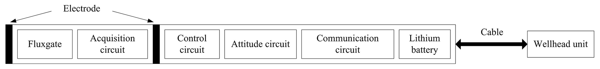
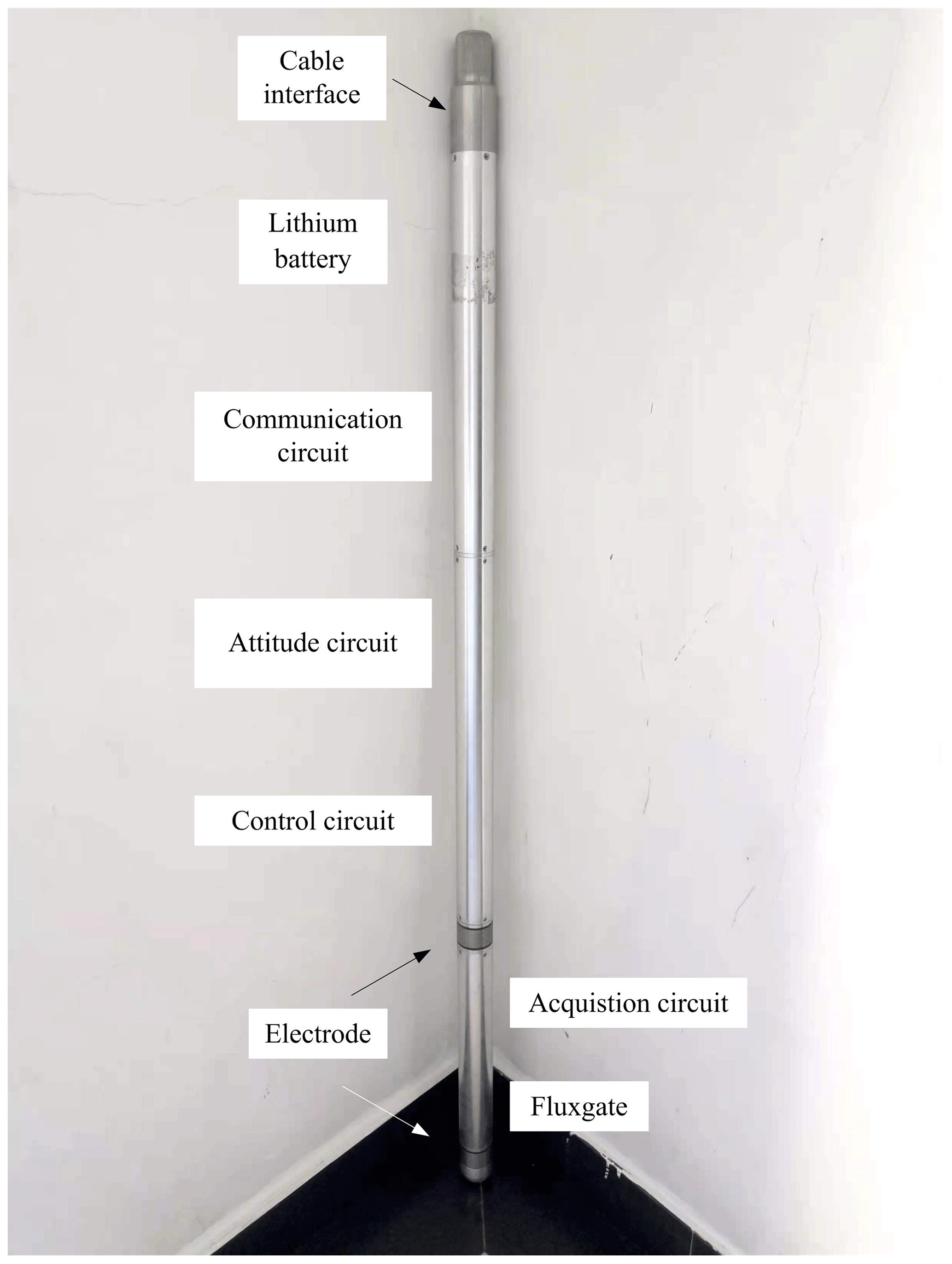
Figure 2Picture of the borehole EMR. The probe top and cable connections communicate with the wellhead unit.
Figure 3 shows a block diagram of the internal hardware architecture of the borehole EMR. The fluxgate performs a high-precision conversion of the three-axis orthogonal magnetic field to the voltage signal, and the voltage is output to the subsequent acquisition circuit. The three-channel voltage signal output from the fluxgate and the voltage signal output from the electrode are then subjected to low-noise amplification, filtering, and analog-to-digital conversion through an acquisition circuit. The attitude circuit includes temperature sensors, accelerometers, and other modules to perform basic status parameter measurements. We used an acorn RISC machine (ARM) and field-programmable gate array (FPGA) together as the main control solution to complete the functions of the unit. This reads the temperature, attitude, and electrical and magnetic information output from the acquisition circuit and performs pre-processing to form a data packet. The data packet is then sent to the communication circuit under the control of the wellhead unit. The communication circuit uses full-duplex communication between the probe tube and the wellhead unit. The time synchronization circuit uses a global positioning system (GPS) and oven-controlled crystal oscillator (OCXO) for time synchronization between the borehole EMRs and the transmitter. The lithium battery supplies power to the borehole EMR. To reduce power supply interference and the weight of the armored cable, the cable is only capable of simple communication and has no power supply function. The capacity of a single lithium battery in the unit is 2.5 Ah. The lithium battery pack is made up of three sections in series that can provide continuous power for nearly 24 h.
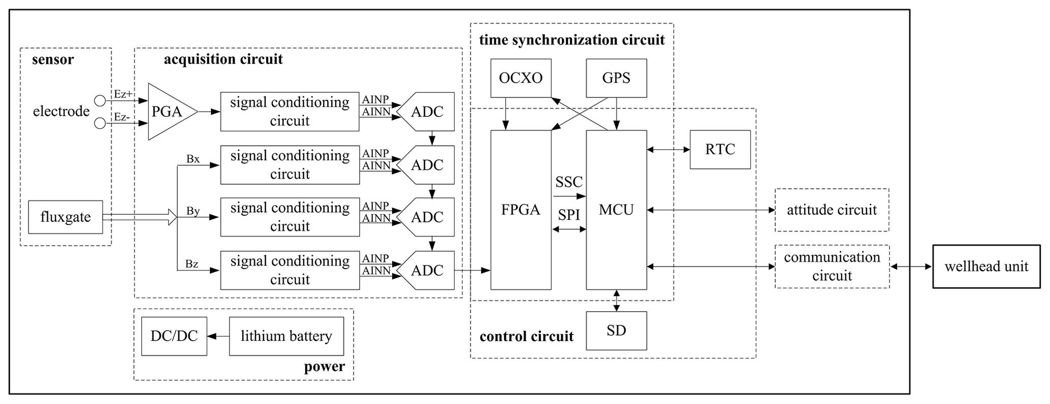
Figure 3Block diagram of the internal hardware architecture of the borehole EMR. The microcontroller unit (MCU) refers to AT91SAM9G45.
2.1 Sensor
2.1.1 Electrode
Studies have shown that Ti and metal salt electrodes such as and CuSO4 are often used for terrestrial observations of electric fields. The and CuSO4 electrodes have stable polarization potential differences and a strong consistency (Petiau, 2000). However, a borehole environment has high temperatures, high pressures, and severe corrosion. For the signal-to-noise ratio of the signal observation to be within the measurement requirements, we selected a Ti electrode with a small potential difference and stability as the electric field sensor. In addition, the electrode has high temperature resistance, high strength, high hardness, and strong corrosion resistance, which are important for adapting to the borehole environment. The electrode is integrated into the borehole EMR and is mounted at the bottom of the borehole EMR unit. It is small in size, with an outer diameter of 50 mm and a height of 30 mm. The dipole length between the two electrodes is 50 cm.
2.1.2 Magnetometer
To measure the magnetic field, fluxgates, induction coils, optically pumped magnetometers, proton magnetometers, superconducting quantum interference devices (SQUIDs), giant magnetoresistances (GMRs), and giant magnetoimpedances (GMIs), among others, are often used. We used a fluxgate sensor that is currently one of the best choices for field applications. The fluxgate sensor is more robust than an induction coil sensor for borehole observations made while in motion. The measuring object of the optically pumped magnetometer and proton magnetometer is a scalar, whereas a fluxgate can measure a vector. Compared to unshielded high-temperature SQUIDs, fluxgates may have a similar noise level; however, their measurement range is much wider (Paperno, 2004). GMI and GMR have low precision and high noise. The fluxgate magnetometers are easy to use, have small volumes, and are inexpensive. Fluxgate sensors also have high resolutions (up to 10−11 T) and wide magnetic field measurement ranges (below 10−8 T), which make them suitable for use with CSEM methods. The Bartington Instruments Mag-03MSESL (United Kingdom) was ideal for our borehole EMR unit. Its noise level is below 6 at 1 Hz. In addition, it can be powered from any ±12 V supply and its outputs are in the form of three analog voltages from 0 to ±10 V proportional to Bx, By, and Bz. The bandwidth is DC −3 kHz. A square sensor allows for easy setup in the field and offers a better axis alignment error, and a measuring range of ±100 µT allows the entire magnetic field of the Earth to be measured.
2.2 Acquisition circuit
The acquisition circuit contains amplifiers, filters, and analog-to-digital conversions used to acquire the Ez component and the orthogonal three-axis magnetic field signals.
Because the type and range of the electrode output signals and the magnetometer output signals are different, there are differences in the principle of the electric and magnetic field signal acquisition channels. The electric field signal originates from the potential difference between the two electrodes and belongs to the differential signal. Owing to the size limitation of the probe, the dipole length between the two electrodes is short, and the signal input of the channel is extremely weak, with an input range of ±4–±250 mVpp. Therefore, to obtain a signal with a signal-to-noise ratio that satisfies the required signal, the channel signal is amplified by a pre-amplifier and a programmable amplifier with a 10× gain. The low-pass network is placed at the input to the instrumentation amplifier for filtering; this filters out the common-mode signals as much as possible, preserves the differential-mode signals, and increases the common-mode rejection ratio. The magnetic field signal is simply attenuated because the fluxgate sensor is directly converted to a single-ended voltage signal output, with a range of ±10 V.
Using electrical isolation can effectively reduce the interference between the analog and digital circuits. The acquisition circuit is connected to the control circuit through an isolated gate driver to ensure the proper transmission of clock signals, configuration commands, and data. The output stages of the four analog-to-digital converters (ADCs) are daisy-chained, effectively reducing the use of line connections and isolation circuitry. The FPGA provides synchronization for simultaneous multi-channel data acquisition.
2.3 Control circuit
The control circuit contains the following parts: FPGA, ARM, OCXO, real-time clock (RTC), and a secure digital memory card (SD). The control circuit uses a combination of the ARM and FPGA to implement packing, reading, storing, transmitting, collecting circuit, and basic data status extraction.
The FPGA (EP4CE22F17C8N from Intel, United States) is the bridge between the ARM and the analog acquisition circuits. It is directly connected to the acquisition circuit through an IO interface to control the logic and timing relationships. The FPGA also provides the main clock and synchronization signals for the analog-to-digital converter (ADS1271 from Analog Devices, United States), configures the sampling rate and gain, receives the serial data sent by the acquisition circuit, and packages and sends the data to the ARM controller. In addition, through the spread spectrum clock (SSC) bus, the serial peripheral interface (SPI) bus and the parallel IO interface complete the bi-directional communication with the ARM, send data to the ARM through the SSC bus, receive configuration commands sent by the ARM through the SPI bus, and complete the acquisition circuit.
The ARM uses an AT91SAM9G45 (Atmel, United States) industrial-grade processor. This processor is based on the ARM926EJ-S and uses the Harvard architecture. The instructions and data belong to different buses, which can be processed in parallel. The working frequency extends to 400 MHz. As part of the borehole EMR controller, the ARM mainly performs the following functions: (1) time keeping, (2) data acquisition and storing data on the SD card, and (3) communication with the wellhead unit.
2.4 Time synchronization circuit
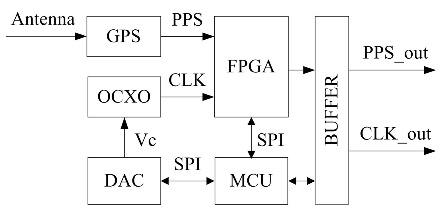
In the exploration process, there are multiple acquisition locations, which means that multiple receivers work together. The transmitter and receiver adopt a distributed design in the borehole electromagnetic detection system; therefore, it is necessary to synchronize timing between each borehole EMR and its transmitter. Figure 4 shows a block diagram of the time synchronization technology used. We used GPS and OCXO as the synchronization reference signals to complete time synchronization (Banerjee et al., 2007). As time changes, there is a small amount of change in the clock frequency. We use the MCU (AT91SAM9G45) to control the digital-to-analog converter (DAC) to feed back a voltage amount for correction, which meets the clock accuracy requirements for borehole electromagnetic measurements. After each borehole EMR has been synchronized, the relative time error between the units depends only on the clock stability of the crystal used inside the borehole EMR. The current oven-controlled crystal oscillator has a clock stability of ; testing reveals that the time error is less than 10 µs. To monitor the signal acquisition status of the electromagnetic receiver in the borehole and observe whether there is data loss, we set a timestamp to write the synchronous clock information to a fixed length block of data. One method is for our synchronous clock to use the 24 kHz clock signal for continuous counting, which is read every time a fixed length of electromagnetic field data is acquired. Time synchronization technology ensures that the borehole EMR time and reference GPS signal remain accurate and consistent, providing a uniform time coordinate for data post-processing.
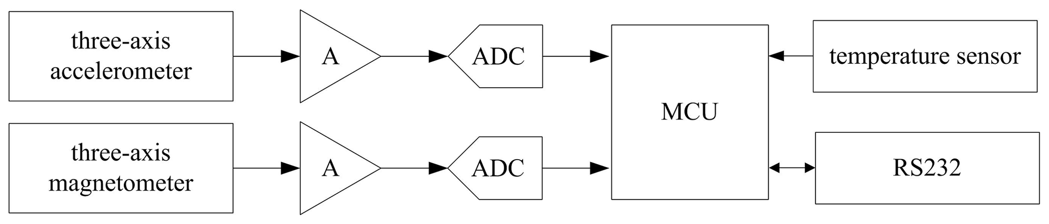
2.5 Attitude circuit
The attitude circuit measures the attitude of the electromagnetic receiver in the borehole. The attitude information includes pitch, roll, and yaw angles. In surface studies, the fluxgate can be placed in a specific direction on the ground; however, this is difficult to achieve in a borehole. Therefore, when measuring the three-axis magnetic field signal in real time in the borehole, it is also necessary to measure the attitude angle of the borehole EMR to determine attitude information. The size and direction of the magnetic field are determined using the coordinate transformation between the instrument coordinate system and the geodetic coordinate system. Figure 5 shows a block diagram of the hardware in the attitude circuit. The three-axis accelerometer and the three-axis magnetometer are used to obtain the voltage signal. The analog signal is amplified and converted to digital using a signal conditioning circuit. The converted digital signal is angularly converted by the MCU (80C51F320) to obtain its parameters, and, finally, the attitude information is output by the serial port. During the acquisition process, the attitude circuit returns angle information by receiving the data request command, and the attitude information is read once for each fixed length data block. The azimuth measurement range is 0–360∘, and the apex angle measurement range is 0–180∘. One notable issue here is that, to obtain an accurate angle between the three axes of the fluxgate sensor and the field source, a high-precision measurement of the angle is required, and the attitude measurement also requires measurement of the axial direction. The fluxgate measurement axis remains at the same height.
2.6 Communication circuit
The long-distance communication circuit completes the communication between the borehole probe and the wellhead unit to control the borehole probe and its data transmission and to display its status. The general drilling depth is 2000 m, which adds a long-distance communication problem.
There are several available communication solutions for logging instruments, including single-core cable communication, optical fiber communication, the controller area network (CAN) bus network, RS485, and RS422, among others. Single-core cable communication uses coded signals, which increases the complexity of the hardware circuit. Optical fiber communication has the advantage of a fast transmission speed and a large transmission bandwidth, but its cost is high. Compared with the CAN bus network transmission, RS485 and RS422 can transmit over larger distances. Both are differential transmissions, which can effectively suppress interference in the transmission line. However, RS422 is a full-duplex mode and RS485 is a half-duplex mode. Our proposed receiver used a built-in lithium battery and local data storage. The borehole EMR itself has large-capacity data storage and high-speed data throughput; therefore, it does not need to use a cable power supply and a cable to transmit high-capacity data. Only simple control commands and basic status are transmitted through the cable. The rate of signal transmission is not high, at approximately 200 bps. Our comparison found that the four-core cable RS422 communication scheme has the advantages of a low power consumption, strong anti-electromagnetic interference capability, and long communication distance; therefore, it was selected for our unit. When the module runs at a baud rate of 9600 bps, the longest transmission distance reaches 1800 m.
In addition, the RJ-45 interface was configured to meet the high-speed data export through the network cable. When the borehole EMR is on the ground, they can communicate over Ethernet, with a transmission rate of up to 10 MB s−1.
To test the function, performance, and stability of the borehole EMR, a series of laboratory experiments and field tests were conducted. Laboratory testing focused on the noise floor, bandwidth, and nonlinearity error, among others. According to the actual exploration needs of the mining area, the field test conducted CSEM data collection work in a borehole to evaluate the performance of the borehole EMR system.
3.1 Laboratory tests
3.1.1 Noise floor
To determine the noise contribution from the borehole EMR itself, the magnetic field channel input of the receiver was shorted to the ground, while the electrical field channel differential input was shorted. We mainly observed the noise floor level in a frequency range of DC −10 kHz. Following the fast Fourier transform (FFT) calculation, the noise power spectrum density (PSD) shown in Fig. 6 was obtained. Figure 6 shows that the noise floor of the three magnetic field channels was lower than 300 at 1 kHz, and the electric field channel noise floor was approximately 10 at 1 kHz. The fluxgate sensitivity was 100 µV nT−1, which results in magnetic field channel noise less than 3 at 1 kHz. There were almost no peaks in the pass band, except for high interference levels at 50 and 150 Hz.

Figure 6Noise power spectral density. The pink curve represents the electric field channel. The red, black, and blue curves represent the magnetic field channels Bx, By, and Bz, respectively.
3.1.2 Bandwidth
Theoretically, the frequency component of the unit impulse function is uniformly distributed over the entire frequency range; i.e., the frequency component ranges from zero to infinity. According to this principle, we used a narrow pulse signal to approximate the unit impulse signal to complete the acquisition channel bandwidth test. The standard signal generator outputs pulse signals with a pulse width of 20.83 µs that are connected to the electrical and magnetic channels. The pulse signal was continuously acquired for 1 min. Then, the acquired data were subjected to FFT analyses. Figure 7 shows that the −3 dB bandwidth for each channel can reach DC −10 kHz.
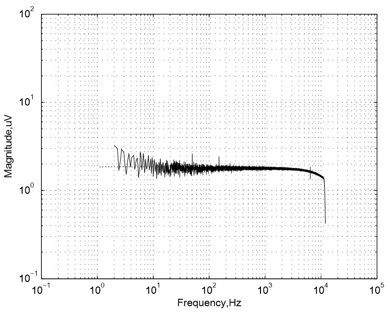
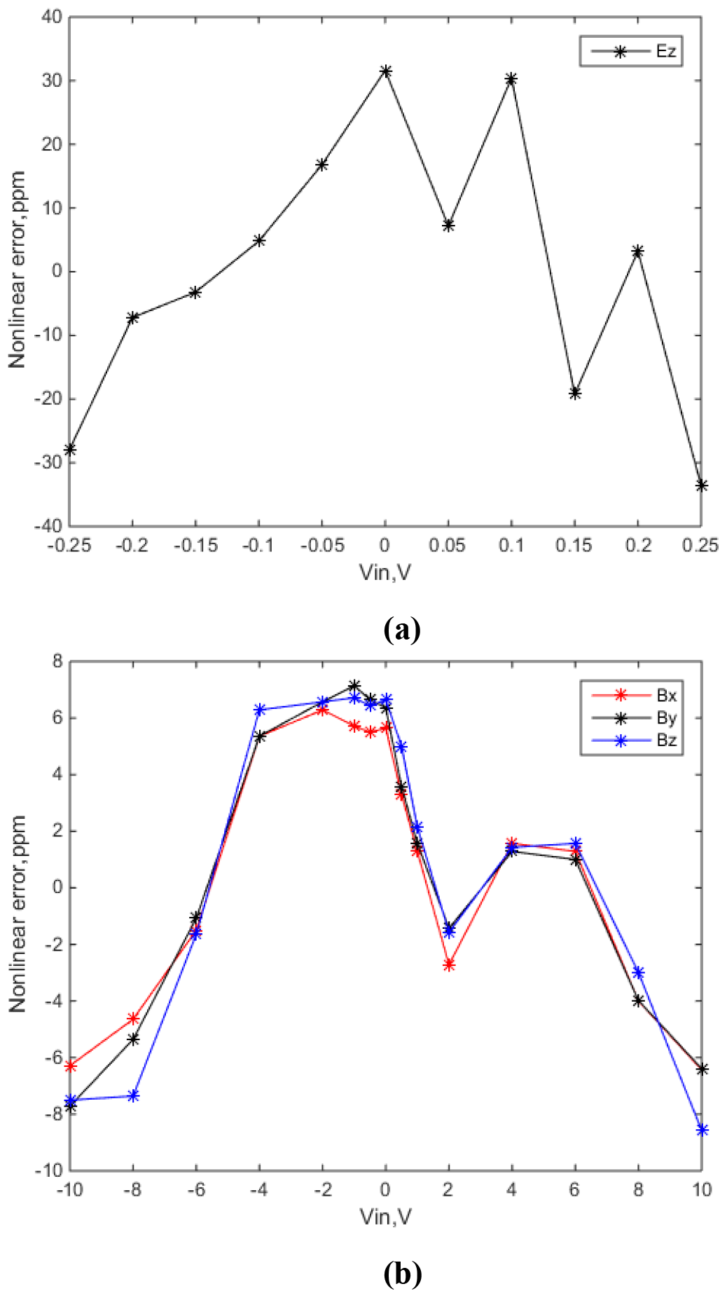
Figure 8Nonlinear errors of channel fitting straight line and the standard voltage curve. (a) Electrical component. (b) Magnetic component.
3.1.3 Nonlinearity error
We also tested the nonlinearity of the borehole EMR that is caused by the signal conditioning circuit and the analog-to-digital converter in the acquisition circuit. The direct current voltage calibration source (Fluke 5720) outputs a series of direct-current voltages, which the receiver receives one by one. The fitted line of the collected voltage values was obtained through least squares fitting, and the deviation between the fitted straight line and the standard voltage curve was calculated to obtain the nonlinear error of the borehole EMR. Because the borehole EMR has different electric and magnetic channel input ranges, we measured them separately. For the electric channel, the high-pass part of the channel band-pass filter was removed, and the output direct-current voltage ranged from −250 to 250 mV. The standard voltage value of 20 mV was equally spaced. This result had a nonlinear error of 33 ppm, as shown in Fig. 8a. For the magnetic channels, the output ranged between −10 and +10 V and had a standard voltage value of 2 V equal intervals. These results are shown in Fig. 8b, and the channel-to-channel consistency is strong. The three-channel nonlinearity errors for the magnetic channels were 6.5, 7.8, and 8.5 ppm.
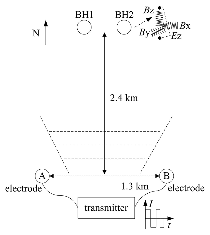
Figure 9Field layout of the experiment. BH1 and BH2 are placed at a certain depth in the borehole. The transmitter and the electrodes are on the ground.
3.2 Field tests
Field observations were conducted to evaluate the field performance of our newly developed borehole EMR. The mine test site was located in Linxi County, Chifeng City, in the Inner Mongolia Autonomous Region, at approximately 43∘N, 118∘E, with an altitude of ∼1 km. Figure 9 shows the field layout of the experiment. To ensure a sufficient signal-to-noise ratio, the transmitter (EMT48) was located 2.4 km south of the test point. The two (A, B) transmitting electrodes were 1.3 km apart. EMT48 is a multi-function borehole ground electromagnetic transmitting system (Wang et al., 2018) from which the maximum power was output continuously for over 8 h, with a power output of more than 48 kW at a current above 60 A. According to the controlled-source audio-frequency magnetotellurics (CSAMT) method, the signal covering the frequency band of 0.9375–9600 Hz was transmitted. One launch circle period lasted 50 min and the maximum current was 50 A. We arranged two borehole EMRs, including BH1 and BH2, for taking simultaneous measurements. The sampling rate was switched according to the transmission frequency and was set to 24 and 2.4 kHz and 150 and 15 Hz.
Table 1Comparison of the performance indicators of available borehole electromagnetic observation equipment. TDEM denotes time domain electromagnetic methods.

First, by performing FFT analyses of all 41 frequency points, we primarily observed the signals of the Ez, Bx, By, and Bz components during a launch cycle. Figure 10 shows the time–frequency spectrum of the signals from BH1 and BH2, from which the expected target frequency can be seen more clearly. The emission source was a horizontal electrical dipole source. In the low-frequency band, the source signal is strong, the signal-to-noise ratio is high, and the frequency signal below 200 Hz is more obvious. As the frequency increases, the signal amplitude attenuation increases and the signal-to-noise ratio decreases. We found that when the frequency of the transmitted signal reached 960 Hz, the acquired signal was attenuated to 6 dB, and signals larger than 1 kHz were essentially unobservable in the frequency domain.

Figure 10Time–frequency spectra. The scale in the figures is provided in dB; however, the data in the figure are calculated using the formula 10log X. The units of the time and frequency are minutes (hh:mm) and Hz, respectively. Owing to the malfunction of the electrode, no obvious signal can be seen in the Ez component of BH1.
When comparing the borehole EMR system proposed in this paper with the performance indicators of the same type of products currently available, as shown in Table 1, existing receivers only measure magnetic field signal information. However, the borehole EMR used in this study innovatively adds electric field signals and synchronously acquires four channels of data, which makes the results increasingly complete and reliable. We observed that our system had obvious advantages in bandwidth, where the highest frequency can reach 10 kHz. The variable sampling rate that is dependent on the transmission frequency is also a key point.
A borehole EMR can record up to four channels of data simultaneously, including the electric and magnetic field signals of Ez, Bx, By, and Bz. The borehole EMR increases the collection of electric field signals, effectively improves the accuracy of data interpretation, and provides technical support for multi-component observations. Our design employed a low-noise data collector to achieve a magnetic field noise less than 6 at 1 kHz, and the electric field noise floor was approximately 20 at 1 kHz. The −3 dB bandwidth of the electric field reached DC −10 kHz, whereas the magnetic field reached DC −3 kHz. Field observations were conducted to evaluate the field performance of the borehole EMR system. All borehole EMRs completed data collection of their acquired data and effectively verified the full waveform synchronous recording of four channels and time synchronization. Results of the experiments show that our system functioned adequately and that high-quality CSEM signals were obtained.
The code used for processing the data in this study is available upon request (2010180031@cugb.edu.cn).
The raw data of this experiment are available upon request (2010180031@cugb.edu.cn).
SXS and MEA designed and tested electronics. SJ was the project leader. MD and KC provided ideas and guidance, including for the experiment. SXS prepared the paper with contributions from all co-authors.
The authors declare that they have no conflict of interest.
We are grateful to Chifeng Lituo Mining Co., Ltd. for supporting the test work.
This research has been supported by the 13th Five-Year National Key R&D Program (grant no. 2017YFF0105704) and 12th Five-Year National 863 Program (grant no. 2014AA06A603).
This paper was edited by Håkan Svedhem and reviewed by two anonymous referees.
Banerjee, P., Suman, Suri, A.K., Chatterjee, A., and Bose, A.: A study on the potentiality of the GPS timing receiver for real time applications, Meas. Sci. Technol., 18, 3811–3815, 2007.
Bartel, L. C. and Jacobson, R. D.: Results of a controlled-source audio frequency magnetotelluric survey at the Puhimau thermal area, Kilauea Volcano, Hawaii, Geophysics, 52, 665–677, 1987.
Bromley, C.: Tensor CSAMT Study of the Fault Zone between Waikite and Te Kopia Geothermal Fields, Earth Planets Space, 45, 887–896, 1993.
Chen, K., Deng, M., Wei, W. B., Jin, S., and Ye, G. F.: New progress in the design and development of AMT instruments, Geophysical and Geochemical Exploration, 37, 78–81, 2013 (in Chinese).
Crone Geophysics: Pulse-EM methods, available at: http://www.cronegeophysics.com/pulse-em/methods/, last access: 1 January 2018.
Duncan, A., Amann, B., O'Keeffe, K., Williams, P., Tully, T., Wellington, A., and Turner, G.: Examples from a new EM and electrical methods receiver system, Explor. Geophys., 29, 347–354, 1998.
Jia, Z. Y. and Jin, F. M.: The Application of surface-borehole electrical Method in reservoir evaluation, Journal of Engineering Geophysics, 3, 326–331, 2008 (in Chinese).
Li, N. M. and Li, D. W.: Overview about depth of investigation on electromagnetic method, The Energy Research and Management Development and Application, 1, 59–61, 2012 (in Chinese).
Li, T. T., Wang, J., and Zhu, K. G.: Research on the exploration depth of the borehole-surface electromagnetic field, Progress in Geophys, 28, 373–379, 2013 (in Chinese).
Paperno, E.: Suppression of magnetic noise in the fundamental-mode orthogonal fluxgate, Sens. Actuators, A, 116, 405–409, 2004.
Petiau, G.: Second Generation of Lead-lead Chloride Electrodes for Geophysical Applications, Pure Appl. Geophys., 157, 357–382, 2000.
Revil, A., Karaoulis, M., Johnson, T., and Kemna, A.: Review: Some low-frequency electrical methods for subsurface characterization and monitoring in hydrogeology, Hydrogeol. J., 4, 617–658, 2012.
Smirnov, T. K., Dynesius, L., and Pedersen, L. B.: Broadband magnetotelluric instruments for near-surface and lithospheric studies of electrical conductivity: A Fennoscandian pool of magnetotelluric instruments, Geophysica, 44, 31–44, 2008.
Tseng, H. W., Wilt, M. J., Becker, A., and Deszcz-Pan, M.: A borehole-to-surface electromagnetic survey, Geophysics, 63, 1565–1572, 1998.
Wang, M., Deng, M., Luo, X. H., Zhao Q. X., Chen, K., and Jing, J. E.: Research on control technology of hardware parallelism for marine controlled source electromagnetic transmitter, J. Geophys. Eng., 15, 62–70, 2018.
Wang, Z. G., He, Z. X., and Wei, W. B.: Fast 3D inversion of borehole ground electrical method data based on born approximation, Chinese J. Geophys., 22, 508–513, 2007 (in Chinese).
Wei, W. B.: New Advance and Prospect of Magnetotelluric Sounding (MT) in China, Progress in Geophysics, 17, 245–254, 2002 (in Chinese).
Wilt, M., Morrison, H. F., Becker, A., Tseng, H. W., Lee, K. H., Torres-Verdin, C., and Alumbaugh, D. L.: Crosshole electromagnetic tomography; a new technology for oil field characterization, The Leading Edge, 14, 173–177, 1995.
Zhu, Z. Y. and Nafi Toksoez, M.: Crosshole seismoelectric measurements in borehole models with fractures, Geophysics, 68, 1519–1524, 2003.